 |
Guide to OpenVMS File Applications
10.1.4 Examining a Sequential File
Figure 10-1 shows the tree structure of a sequential file.
Figure 10-1 Tree Structure for Sequential Files
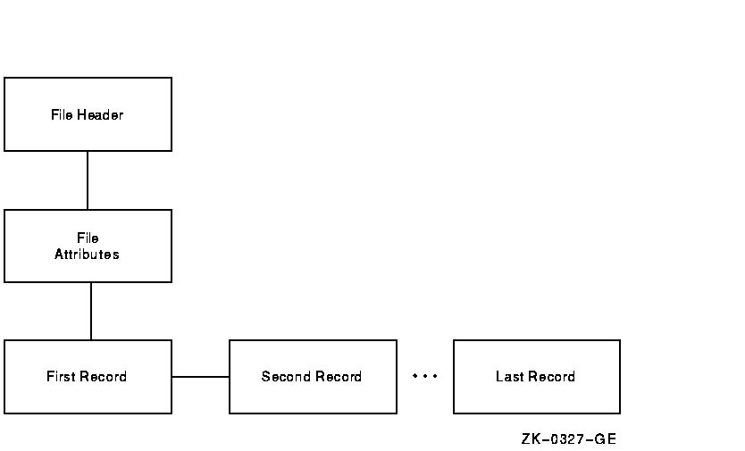
The FILE HEADER structure is always the first structure displayed. From
the FILE HEADER structure, the DOWN command moves the current position
to the FILE ATTRIBUTES structure. The DOWN command from the FILE
ATTRIBUTES structure moves the current position to the first record in
the file. From the first record, the REST command will move the current
position through the records in the file, displaying each one in turn.
A series of NEXT commands will also accomplish this same operation.
Figure 10-2 shows the layout and contents of the records in a
sequential file SEQ.DAT. Example 10-3 is an interactive examination of
SEQ.DAT, showing the contents of three records in the file.
Figure 10-2 Record Layout and Content for SEQ.DAT

| Example 10-3 Examining a Sequential File |
$ ANALYZE/RMS_FILE/INTERACTIVE SEQ.DAT
|
FILE HEADER
       File Spec: DISK$DELPHIWORK:[RMS32]SEQ.DAT;3
       File ID: (1170,2,2)
       Owner UIC: [730,465]
       Protection:  System: RWED, Owner: RWED, Group: RWED, World:
       Creation Date:    7-MAY-1993 16:51:30.92
       Revision Date:    8-MAY-1993 14:02:17.15, Number: 3
       Expiration Date: none specified
       Backup Date:     none posted
       Contiguity Options:  none
       Performance Options: none
       Reliability Options: none
|
RMS FILE ATTRIBUTES
       File Organization: sequential
       Record Format: variable
       Record Attributes:   carriage-return
       Maximum Record Size: 0
       Longest Record: 73
       Blocks Allocated: 3, Default Extend Size: 0
       End-of-File VBN: 1, Offset: %X'00E4'
       File Monitoring: disabled
       Global Buffer Count: 0
|
       DATA BYTES (VBN 1, offset %X'0000'):
                       7  6  5  4  3  2  1  0          01234567
                     ------------------------          --------
                      31 30 30 30 30 30 00 49|  0000  |I.000001|
                      20 4C 41 54 49 47 49 44|  0008  |COMPAQ  |
                      4E 45 4D 50 49 55 51 45|  0010  |COMPUTER|
                      52 4F 50 52 4F 43 20 54|  0018  |CORPORAT|
                      31 31 20 4E 4F 49 54 41|  0020  |ION 110 |
                      42 20 54 49 50 53 20 30|  0028  |SPIT BRO|
                      41 4F 52 20 4B 4F 4F 52|  0030  |OK ROAD |
                      41 55 48 53 41 4E 20 44|  0038  |NASHUA  |
                      33 30 48 4E 20 20 20 20|  0040  |   NH030|
                                  00 31 36 30|  0048  |62.    |
|
       DATA BYTES (VBN 1, offset %X'004C'):
                       7  6  5  4  3  2  1  0          01234567
                     ------------------------          --------
                      32 30 30 30 30 30 00 49|  0000  |I.000002|
                      49 46 46 4F 20 42 44 41|  0008  |ADB OFFI|
                      4C 50 50 55 53 20 45 43|  0010  |CE SUPPL|
                      20 20 20 20 20 53 45 49|  0018  |IES     |
                      32 34 20 20 20 20 20 20|  0020  |      42|
                      4F 4D 45 53 4F 52 20 30|  0028  |0 ROSEMO|
                      45 52 54 53 20 54 4E 55|  0030  |UNT STRE|
                      49 44 20 4E 41 53 54 45|  0038  |ETSAN DI|
                      32 39 41 43 20 4F 47 45|  0040  |EGO CA92|
                                  00 30 31 31|  0048  |110.    |
|
       DATA BYTES (VBN 1, offset %X'0098'):
                       7  6  5  4  3  2  1  0          01234567
                     ------------------------          --------
                      33 30 30 30 30 30 00 49|  0000  |I.000003|
                      52 50 20 52 4F 4C 4F 43|  0008  |COLOR PR|
                      4C 20 47 4E 49 54 4E 49|  0010  |INTING L|
                      52 4F 54 41 52 4F 42 41|  0018  |ABORATOR|
                      34 39 20 20 20 53 45 49|  0020  |IES   94|
                      35 20 54 53 41 45 20 39|  0028  |9 EAST 5|
                      45 45 52 54 53 20 48 54|  0030  |TH STREE|
                      4F 59 20 57 45 4E 20 54|  0038  |T NEW YO|
                      30 31 59 4E 20 20 4B 52|  0040  |RK  NY10|
                                  00 33 30 30|  0048  |003.    |
|
Figure 10-3 shows the tree structure of relative files.
Figure 10-3 Tree Structure of Relative Files
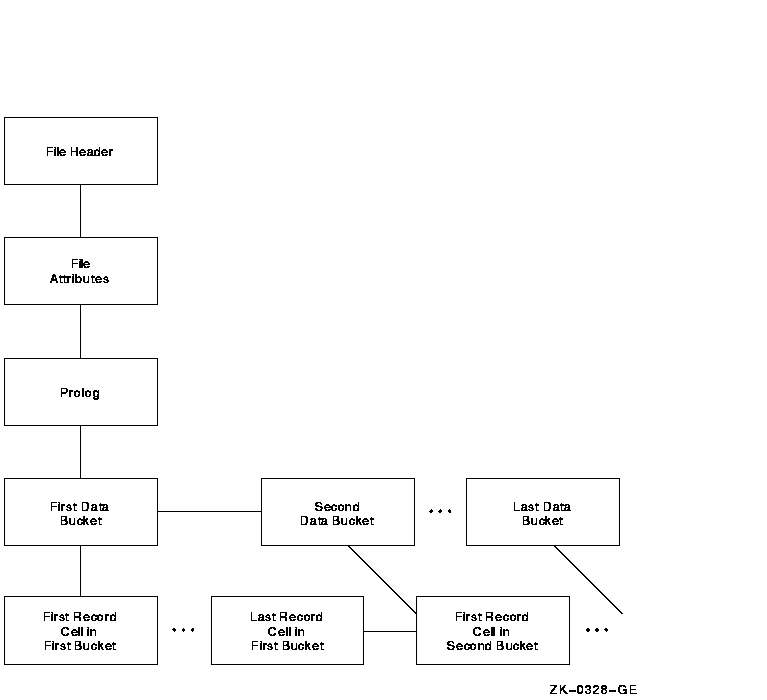
The tree structure of relative files also begins with the FILE HEADER
and FILE ATTRIBUTES structures. From the FILE ATTRIBUTES structure, the
next structure down is the PROLOG. The first structure down from the
PROLOG is the FIRST DATA BUCKET. The data bucket structures can be
examined with the REST command or one at a time with the NEXT command.
The only information at the data bucket level is the number of the data
bucket's virtual block.
The next structure down is the FIRST RECORD CELL IN FIRST BUCKET. You
can examine the records in each cell by specifying either the REST
command or a series of NEXT commands.
Example 10-4 shows an interactive examination of a relative file.
| Example 10-4 Examining a Relative File |
FILE HEADER
       File Spec: DISK$NEWWORK:[RMS32]REL.DAT;1
       File ID: (9573,7,2)
       Owner UIC: [181,065]
       Protection:  System: RWED, Owner: RWED, Group: RE, World:
       Creation Date:   22-MAY-1993 10:42:04.95
       Revision Date:   22-MAY-1993 10:42:05.81, Number: 1
       Expiration Date: none specified
       Backup Date:     none posted
       Contiguity Options:  contiguous-best-try
       Performance Options: none
       Reliability Options: none
|
RMS FILE ATTRIBUTES
       File Organization: relative
       Record Format: variable
       Record Attributes:   carriage-return
       Maximum Record Size: 75
       Blocks Allocated: 9, Default Extend Size: 0
       Bucket Size: 3
       File Monitoring: disabled
       Global Buffer Count: 0
|
FIXED PROLOG
       Prolog Flags:
              (0)  PLG$V_NOEXTEND   0
       First Data Bucket VBN: 2
       Maximum Record Number: 2147483647
       End-of-File VBN: 10
       Prolog Version: 1
|
       RECORD CELL (VBN 2, offset %X'0000'):
              Cell Control Flags:
                     (2)  DLC$V_DELETED    0
                     (3)  DCL$V_REC        1
              Record Bytes:
                       7  6  5  4  3  2  1  0          01234567
                     ------------------------          --------
                      31 30 30 30 30 30 00 49|  0000  |I.000001|
                      20 4C 41 54 49 47 49 44|  0008  |COMPAQL |
                      4E 45 4D 50 49 55 51 45|  0010  |COMPUTER|
                      52 4F 50 52 4F 43 20 54|  0018  |CORPORAT|
                      31 31 20 4E 4F 49 54 41|  0020  |ION  110|
                      42 20 54 49 50 53 20 30|  0028  |SPIT BRO|
                      41 4F 52 20 4B 4F 4F 52|  0030  |OK ROAD |
                      41 55 48 53 41 4E 20 44|  0038  |NASHUA  |
                      33 30 48 4E 20 20 20 20|  0040  |   NH030|
                                     31 36 30|  0048  | 62     |
|
If you use the REST command at the CELL AND RECORD level, the utility
will display all the cells and records in the file, not just the cells
and records in the current bucket.
The structure of an indexed file also begins with the FILE HEADER, FILE
ATTRIBUTES, and PROLOG structures. From the PROLOG structure, the file
structure branches to the area descriptors and the key descriptors. To
branch to the area descriptor path, specify the command DOWN AREA. To
branch to the key descriptor path, specify DOWN KEY.
The area descriptor path contains structures that show information
about the various areas in the file. The key descriptor path contains
the primary key structures (and data records) and any secondary key
structures.
Figure 10-4 shows the structure following the area descriptor path.
Figure 10-4 Area Descriptor Path
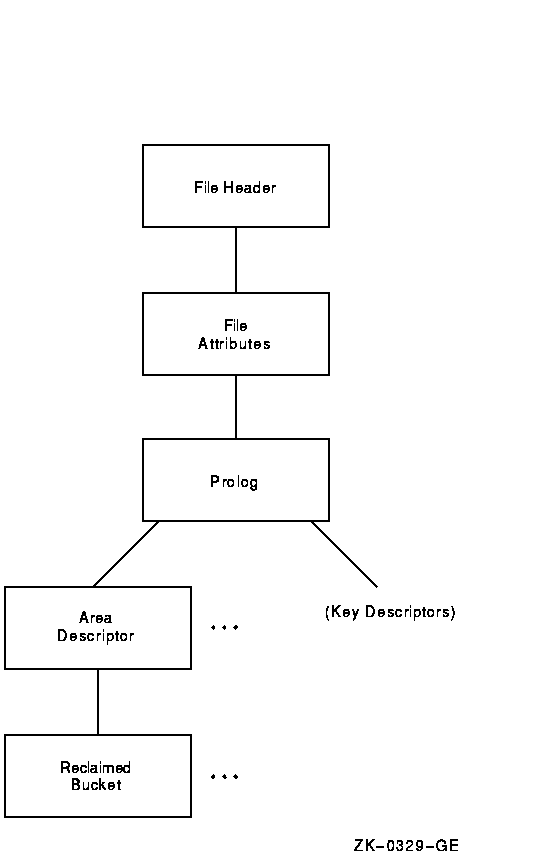
Example 10-5 shows an examination of an area descriptor path from the
PROLOG level.
| Example 10-5 Examining an Area Descriptor
Path |
AREA DESCRIPTOR #0 (VBN 3, offset %X'0000'))
       Bucket Size: 1)
       Alignment: AREA$C_NONE)
       Alignment Flags:)
              (0)  AREA$V_HARD      0)
              (1)  AREA$V_ONC       0)
              (5)  AREA$V_CBT       0)
              (7)  AREA$V_CTG       0)
       Current Extent Start: 1, Blocks: 9, Used: 7, Next: 8)
       Default Extend Quantity: 0)
|
Figure 10-5 shows the structure following the key descriptor path. As
shown in the figure, you can branch directly to the DATA BUCKET, or you
can branch to the INDEX ROOT BUCKET to begin examination of the index
structure, eventually reaching the DATA BUCKET structure.
Depending on whether you are examining the primary index structure or
one of the alternate index structures, there is a difference in the
contents of the record structure.
The PRIMARY RECORD structure contains the actual data records; the
ALTERNATE RECORD structures contain secondary index data records
(SIDRs).
Figure 10-5 Key Descriptor Path
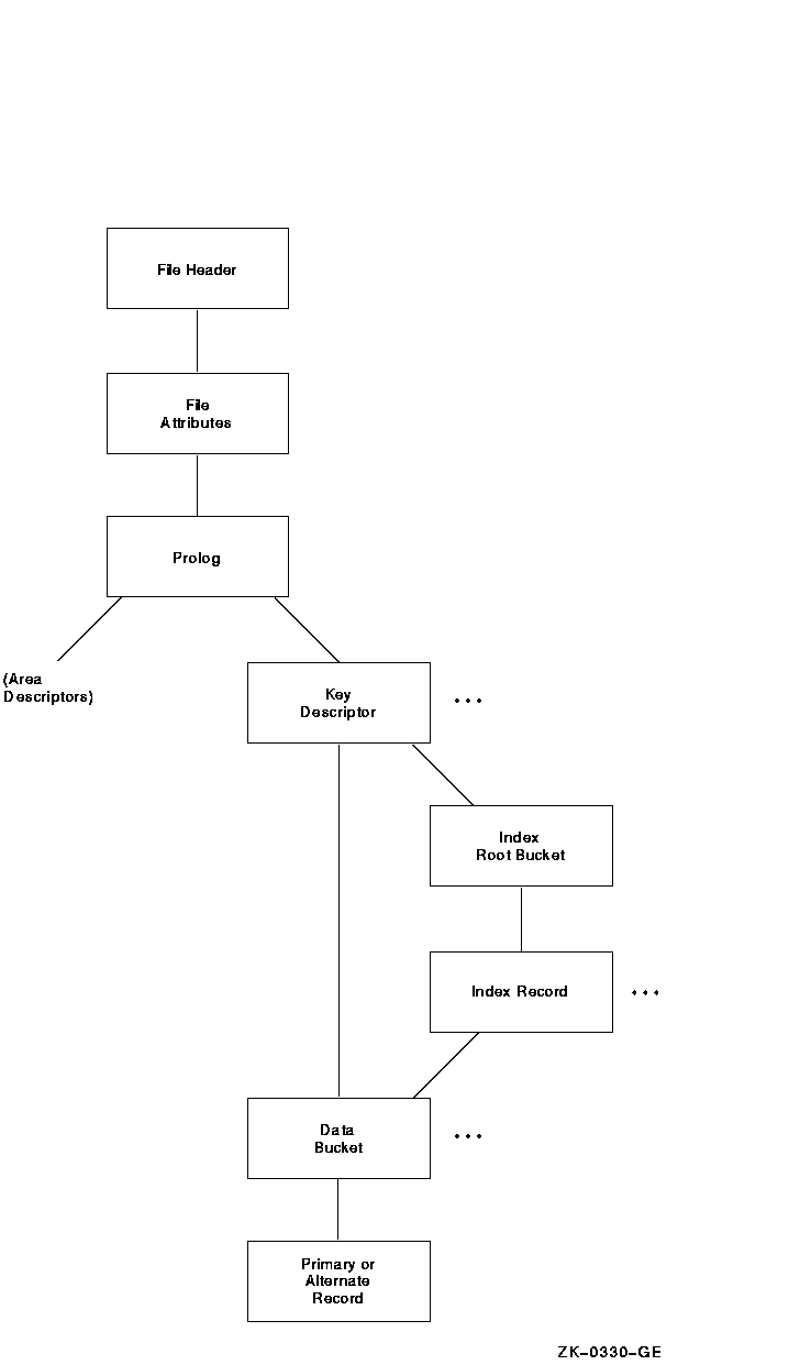
Figure 10-6 displays the structure of the primary records.
Figure 10-6 Structure of Primary Records
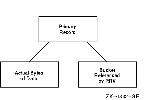 As shown in Figure 10-6, the branch from the primary record structure
allows you to either examine the actual bytes of data within the record
or to follow the RRV.
Example 10-6 shows an examination of a primary record.
| Example 10-6 Examining a Primary Record |
       PRIMARY DATA RECORD (VBN 4, offset %X'000E')
       Record Control Flags:
              (2)  IRC$V_DELETED    0
              (3)  IRC$V_RRV        0
              (4)  IRC$V_NOPTRSZ    0
       Record ID: 1
       RRV ID: 1, 4-Byte Bucket Pointer: 4
       Key:
                7  6  5  4  3  2  1  0          01234567
              ------------------------          --------
                     31 30 30 30 30 30|  0000  |000001  |
|
         7  6  5  4  3  2  1  0          01234567
       ------------------------          --------
        31 30 30 30 30 30 00 49|  0000  |I.000001|
        20 4C 41 54 49 47 49 44|  0008  |COMPAQ  |
        4E 45 4D 50 49 55 51 45|  0010  |COMPUTER|
        52 4F 50 52 4F 43 20 54|  0018  |CORPORAT|
        31 31 20 4E 4F 49 54 41|  0020  |ION 110 |
        42 20 54 49 50 53 20 30|  0028  |SPIT BRO|
        41 4F 52 20 4B 4F 4F 52|  0030  |OK ROAD |
        41 55 48 53 41 4E 20 44|  0038  |NASHUA  |
        33 30 48 4E 20 20 20 20|  0040  |    NH03|
                       31 36 30|  0048  |062     |
|
       PRIMARY DATA RECORD (VBN 4, offset %X'000E')
              Record Control Flags:
                     (2)  IRC$V_DELETED    0
                     (3)  IRC$V_RRV        0
                     (4)  IRC$V_NOPTRSZ    0
              Record ID: 1
              RRV ID: 1, 4-Byte Bucket Pointer: 4
              Key:
                       7  6  5  4  3  2  1  0          01234567
                     ------------------------          --------
                            31 30 30 30 30 30|  0000  |000001  |
|
BUCKET HEADER (VBN 4)
       Check Character: %X'00'
       Area Number: 0
       VBN Sample: 4
       Free Space Offset: %X'0104'
       Free Record ID Range: 4 - 255
       Next Bucket VBN: 4
       Level: 0
       Bucket Header Flags:
              (0)  BKT$V_LASTBKT    1
              (1)  BKT$V_ROOTBKT    0
|
Figure 10-7 displays the structure of the alternate records.
Figure 10-7 Structure of Alternate Records
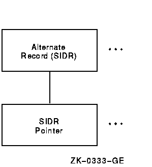
Example 10-7 shows an examination of an alternate record.
| Example 10-7 Examining an Alternate
Record |
SIDR RECORD (VBN 6, offset %X'000E')
       Control Flags:
              (4)  IRC$V_NOPTRSZ    0
       Record ID: 1
       Key:
                7  6  5  4  3  2  1  0          01234567
              ------------------------          --------
                        31 36 30 33 30|  0000  |03062   |
|
              sidr pointer control flags:
                     (2)  IRC$V_DELETED    0
                     (5)  IRC$V_KEYDELETE  0
              sidr pointer record id: 1, 4-byte record VBN: 4
|
10.2 Generating an FDL File from a Data File
You can use the Analyze/RMS_File utility to create an FDL file
generally called an analysis file. FDL files created by
ANALYZE/RMS_FILE contain statistics about each area and key in the
primary sections named ANALYSIS_OF_AREA and ANALYSIS_OF_KEY.
These analysis sections are then used by the Edit/FDL utility in its
Optimize script. You can compare the statistics in these sections with
your assumptions about the file's use; you may find some places in the
file's structure where additional tuning will be possible.
To generate an FDL file from a data file, use the following command
syntax:
ANALYZE/RMS_FILE/FDL filespec
|
With a command of this type, the FDL file obtains its file name from
the input file specification; to assign a different file name, use the
/OUTPUT qualifier. For example, the following command would generate an
FDL file named INDEXDEF.FDL from the data file CUSTFILE.DAT:
$ ANALYZE/RMS_FILE/FDL/OUTPUT=INDEXDEF CUSTFILE.DAT
|
Example 10-8 shows an FDL file showing the KEY and ANALYSIS_OF_KEY
sections for an indexed file with two keys.
| Example 10-8 KEY and ANALYSIS_OF_KEY Sections
in an FDL File |
IDENT        2-JUN-1993 16:15:35       VMS ANALYZE/RMS_FILE Utility

SYSTEM
       SOURCE                  VMS
FILE
       ALLOCATION              9
       BEST_TRY_CONTIGUOUS     no
       BUCKET_SIZE             1
       CONTIGUOUS              no
       EXTENSION               0
       GLOBAL_BUFFER_COUNT     0
       NAME                    DISK$USERWORK:[WORK.RMS32]CUSTDATA.DAT;4
       ORGANIZATION            indexed
       OWNER                   [520,50]
       PROTECTION              (system:RWED, owner:RWED, group:RWED, world:)
       READ_CHECK              no
       WRITE_CHECK             no

RECORD
       BLOCK_SPAN              yes
       CARRIAGE_CONTROL        carriage_return
       FORMAT                  variable
       SIZE                    0

AREA 0
       BEST_TRY_CONTIGUOUS     no
       BUCKET_SIZE             1
       CONTIGUOUS              no
       EXTENSION               0

KEY 0
       CHANGES                 no
       DATA_AREA               0
       DATA_FILL               100
       DUPLICATES              no
       INDEX_AREA              0
       INDEX_FILL              100
       LEVEL1_INDEX_AREA       0
       NULL_KEY                no
       PROLOG                  1
       SEG0_LENGTH             6
       SEG0_POSITION           0
       TYPE                    string
KEY 1
       CHANGES                 no
       DATA_AREA               0
       DATA_FILL               100
       DUPLICATES              yes
       INDEX_AREA              0
       INDEX_FILL              100
       LEVEL1_INDEX_AREA       0
       NULL_KEY                no
       SEG0_LENGTH             5
       SEG0_POSITION           68
       TYPE                    string

ANALYSIS_OF_AREA 0
       RECLAIMED_SPACE         0

ANALYSIS_OF_KEY 0
       DATA_FILL               50
       DATA_RECORD_COUNT       3
       DATA_SPACE_OCCUPIED     1
       DEPTH                   1
       INDEX_FILL              4
       INDEX_SPACE_OCCUPIED    1
       MEAN_DATA_LENGTH        73
       MEAN_INDEX_LENGTH       9

ANALYSIS_OF_KEY 1
       DATA_FILL               14
       DATA_RECORD_COUNT       3
       DATA_SPACE_OCCUPIED     1
       DEPTH                   1
       DUPLICATES_PER_SIDR     1
       INDEX_FILL              4
       INDEX_SPACE_OCCUPIED    1
       MEAN_DATA_LENGTH        19
       MEAN_INDEX_LENGTH       8
|
10.3 Optimizing and Redesigning File Characteristics
To maintain your files properly, you must occasionally tune them. Tuning
involves adjusting and readjusting the characteristics of the file,
generally to make the file run faster or more efficiently, and then
reorganizing the file to reflect those changes.
There are two ways to tune files. You can redesign your FDL file to
change file characteristics or parameters. You can change these
characteristics either interactively with the Edit/FDL utility (the
preferred method) or by using a text editor. With the redesigned FDL
file, then, you can create a new data file.
You can also optimize your data file by using ANALYZE/RMS_FILE with the
/FDL qualifier. This method, rather than actually redesigning your FDL
file, produces an FDL file containing certain statistics about the
file's use that you can then use to tune your existing data file.
Figure 10-8 shows how to use the RMS utilities to perform the tuning
cycle.
Figure 10-8 RMS Tuning Cycle
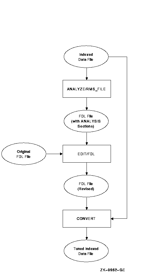
Section 10.3.1 describes how to redesign an FDL file, and Section 10.3.2
explains how to optimize the run-time performance of a data file.
There are many ways to redesign an FDL file. If you want to make small
changes, you can use the ADD, DELETE, and MODIFY commands at the main
menu (main editor) level.
| Command |
Function |
|
ADD
|
Allows you to add one or more new lines to the FDL file. When you give
the ADD command at the main menu level, the Edit/FDL utility prompts
you with a menu displaying all legal primary attributes; your FDL file
does not necessarily have to contain all these attributes. You can add
a new primary attribute to your file, or you can add a new secondary
attribute to an existing primary attribute.
When you type in a primary attribute, the Edit/FDL utility displays
all the legal secondary attributes for that primary attribute with
their possible values. You can then select the secondary attribute that
you want to add to your FDL file and supply the appropriate value for
the secondary attribute.
|
|
DELETE
|
Allows you to delete one or more lines from the FDL file. When you give
the DELETE command at the main menu level, the Edit/FDL utility prompts
you with a menu displaying the current primary attributes of your FDL
file.
When you select the primary attribute for the attribute you want to
remove from your FDL definition, the Edit/FDL utility displays the
current values for all of the FDL file's secondary attributes. When you
select the appropriate secondary from this list, the Edit/FDL utility
removes it from the FDL definition. If you delete all of the secondary
attributes of a primary attribute, the Edit/FDL utility removes the
primary attribute from the current definition.
|
|
MODIFY
|
Allows you to change an existing line in the FDL definition. When you
issue the MODIFY command at the main menu level, the Edit/FDL utility
prompts you with a menu displaying the current primary attributes of
your FDL file.
When you type in a primary attribute, the Edit/FDL utility displays
all the existing secondary attributes for that primary attribute with
their current values. You can then select the secondary attribute of
which you want to change the value and then supply the appropriate
value for the secondary attribute.
|
However, if you want to make substantial changes to an FDL file, you
should invoke the Touch-up script. Because sequential and relative
files are simple in design, the Touch-up script works only with FDL
files that describe indexed files. If you want to redesign sequential
and relative files, you can use the command listed above (ADD, DELETE,
or MODIFY), or you can go through the design phase again, using the
scripts for those organizations.
To completely redesign an existing FDL file that describes an indexed
sequential file, use the following command syntax:
EDIT/FDL/SCRIPT=TOUCHUP fdl-filespec
|
|


 As shown in Figure 10-6, the branch from the primary record structure
allows you to either examine the actual bytes of data within the record
or to follow the RRV.

