[an error occurred while processing this directive]

HP OpenVMS Systems Documentation

Content starts here

OpenVMS Programming Concepts Manual


Previous Contents Index

24.7.4 Inserting an Entry into a Balanced Binary Tree

Three routines allow you to manipulate the contents of a balanced binary tree:

  • LIB$INSERT_TREE adds an entry to a balanced binary tree.
  • LIB$LOOKUP_TREE looks up an entry in a balanced binary tree.
  • LIB$TRAVERSE_TREE calls an action routine for each node in the tree.

Example

The following BLISS example illustrates all three routines. The program prompts for input from SYS$INPUT and stores each data line as an entry in a binary tree. When the user enters the end-of-file character (Ctrl/Z), the tree is printed in sorted order. The program includes three subroutines:

  • The first subroutine allocates virtual memory for a node.
  • The second subroutine compares a key with a node.
  • The third subroutine is called during the tree traversal. It prints out the left and right subtree pointers, the current node balance, and the name of the node.


%TITLE 'TREE_EXAMPLE   - Sample program using binary tree routines'
MODULE TREE_EXAMPLE(                      ! Sample program using trees
                IDENT = '1-001',
                MAIN = TREE_START
                ) =
BEGIN

%SBTTL 'Declarations'
!+
! SWITCHES:
!-
SWITCHES ADDRESSING_MODE (EXTERNAL = GENERAL, NONEXTERNAL = WORD_RELATIVE);

!+
! LINKAGES:
!
!      NONE
!
! TABLE OF CONTENTS:
!-

FORWARD ROUTINE
    TREE_START,                     ! Main program
    ALLOC_NODE,                     ! Allocate memory for a node
    COMPARE_NODE,                   ! Compare two nodes
    PRINT_NODE;                     ! Print a node (action routine
                                    !  for LIB$TRAVERSE_TREE)

!+
! INCLUDE FILES:
!-

LIBRARY 'SYS$LIBRARY:STARLET.L32';              ! System symbols

!+
! Define VMS block structures (BLOCK[,BYTE]).
!-
STRUCTURE
    BBLOCK [O, P, S, E; N] =
                [N]
                (BBLOCK + O) <P, S, E>;
!+
! MACROS:
!-
MACRO
    NODE$L_LEFT = 0,0,32,0%,         ! Left subtree pointer in node
    NODE$L_RIGHT = 4,0,32,0%,        ! Right subtree pointer
    NODE$W_BAL = 8,0,16,0%,          ! Balance this node
    NODE$B_NAMLNG = 10,0,8,0%,       ! Length of name in this node
    NODE$T_NAME = 11,0,0,0%;         ! Start of name (variable length)

LITERAL
    NODE$C_LENGTH = 11;              ! Length of fixed part of node

!+
! EXTERNAL REFERENCES:
!-

EXTERNAL ROUTINE
    LIB$GET_INPUT,                   ! Read from SYS$INPUT
    LIB$GET_VM,                      ! Allocate virtual memory
    LIB$INSERT_TREE,                 ! Insert into binary tree
    LIB$LOOKUP_TREE,                 ! Lookup in binary tree
    LIB$PUT_OUTPUT,                  ! Write to SYS$OUTPUT
    LIB$TRAVERSE_TREE,               ! Traverse a binary tree
    STR$UPCASE,                      ! Convert string to all uppercase
    SYS$FAO;                         ! Formatted ASCII output routine

%SBTTL 'TREE_START - Sample program main routine';
ROUTINE TREE_START =
BEGIN
!+
! This program reads from SYS$INPUT and stores each data line
! as an entry in a binary tree.  When end-of-file character (CTRL/Z)
! is entered, the tree will be printed in sorted order.
!-
LOCAL
    NODE : REF BBLOCK,              ! Address of allocated node
    TREEHEAD,                       ! List head of binary tree
    LINEDESC : BBLOCK[DSC$C_S_BLN], ! String descriptor for input line
    STATUS;

TREEHEAD = 0;                           ! Zero binary tree head
CH$FILL(0,DSC$C_S_BLN,LINEDESC);        ! Make a dynamic descriptor
LINEDESC[DSC$B_CLASS] = DSC$K_CLASS_D;  ! ...
!+
! Read input lines until end of file seen.
!-
WHILE (STATUS = LIB$GET_INPUT(LINEDESC,           ! Read input line
                        $DESCRIPTOR('Text: ')))   !  with this prompt
                NEQ RMS$_EOF
DO IF NOT .STATUS                            ! Report any errors found
        THEN SIGNAL(.STATUS)
        ELSE BEGIN
            STR$UPCASE(LINEDESC,LINEDESC);   ! Convert string
                                             !  to uppercase
            IF NOT (STATUS = LIB$INSERT_TREE(
                        TREEHEAD,       ! Insert good data into the tree
                        LINEDESC,       ! Data to insert
                        %REF(1),        ! Insert duplicate entries
                        COMPARE_NODE,   ! Addr. of compare routine
                        ALLOC_NODE,     ! Addr. of node allocation routine
                        NODE,           ! Return addr. of
                        0))             !   allocated node here
                THEN SIGNAL(.STATUS);
            END;
!+
! End of file character encountered.  Print the whole tree and exit.
!-
IF NOT (STATUS = LIB$TRAVERSE_TREE(
                        TREEHEAD,       ! Listhead of tree
                        PRINT_NODE,     ! Action routine to print a node
                        0))
    THEN SIGNAL(.STATUS);

RETURN SS$_NORMAL
END;                                     ! End of routine tree_start

ROUTINE ALLOC_NODE (KEYDESC,RETDESC,CONTEXT) =
BEGIN
!+
! This routine allocates virtual memory for a node.
!
! INPUTS:
!
!      KEYDESC                Address of string descriptor for key
!                              (this is the linedesc argument passed
!                              to LIB$INSERT_TREE)
!      RETDESC                Address of location to return address of
!                              allocated memory
!      CONTEXT                Address of user context argument passed
!                              to LIB$INSERT_TREE (not used in this
!                              example)
!
! OUTPUTS:
!
!        Memory address returned in longword pointed to by retdesc
!-
MAP
    KEYDESC : REF BBLOCK,
    RETDESC : REF VECTOR[,LONG];

LOCAL
    NODE : REF BBLOCK,
    STATUS;

STATUS = LIB$GET_VM(%REF(NODE$C_LENGTH+.KEYDESC[DSC$W_LENGTH]),NODE);
IF NOT .STATUS
    THEN RETURN .STATUS
    ELSE BEGIN
        NODE[NODE$B_NAMLNG] = .KEYDESC[DSC$W_LENGTH];  ! Set name length
        CH$MOVE(.KEYDESC[DSC$W_LENGTH],                ! Copy in the name
                .KEYDESC[DSC$A_POINTER],
                NODE[NODE$T_NAME]);
        RETDESC[0] = .NODE;                    ! Return address to caller
        END;
RETURN .STATUS

END;


ROUTINE COMPARE_NODE (KEYDESC,NODE,CONTEXT) =
BEGIN
!+
! This routine compares a key with a node.
!
! INPUTS:
!
!       KEYDESC           Address of string descriptor for new key
!                          (This is the linedesc argument passed to
!                          LIB$INSERT_TREE)
!       NODE              Address of current node
!       CONTEXT           User context data (Not used in this example)
!-
MAP
    KEYDESC : REF BBLOCK,
    NODE : REF BBLOCK;

RETURN CH$COMPARE(.KEYDESC[DSC$W_LENGTH],          ! Compare key with
                                                   !  current node
                        .KEYDESC[DSC$A_POINTER],
                        .NODE[NODE$B_NAMLNG],
                        NODE[NODE$T_NAME])

END;

ROUTINE PRINT_NODE (NODE,CONTEXT) =
BEGIN
!+
! This routine is called during the tree traversal.  It
! prints out the left and right subtree pointers, the
! current node balance, and the name of the node.
!-
MAP
    NODE : REF BBLOCK;

LOCAL
    OUTBUF : BBLOCK[512],                   ! FAO output buffer
    OUTDESC : BBLOCK[DSC$C_S_BLN],          ! Output buffer descriptor
    STATUS;
CH$FILL(0,DSC$C_S_BLN,OUTDESC);             ! Zero descriptor
OUTDESC[DSC$W_LENGTH] = 512;
OUTDESC[DSC$A_POINTER] = OUTBUF;
IF NOT (STATUS = SYS$FAO($DESCRIPTOR('!XL !XL !XL !XW !AC'),
                        OUTDESC,OUTDESC,
                        .NODE,.NODE[NODE$L_LEFT],
                        .NODE[NODE$L_RIGHT],
                        .NODE[NODE$W_BAL],
                        NODE[NODE$B_NAMLNG]))
    THEN SIGNAL(.STATUS)
    ELSE BEGIN
        STATUS = LIB$PUT_OUTPUT(OUTDESC);      ! Output the line
        IF NOT .STATUS
            THEN SIGNAL(.STATUS);
        END;

RETURN SS$_NORMAL

END;
END                                       ! End of module TREE_EXAMPLE

ELUDOM


Chapter 25
Using Cross-Reference Routines

The cross-reference routines are contained in a separate, shareable image capable of creating a cross-reference analysis of symbols. They accept cross-reference data, summarize it, and format it for output. Two facilities that use the cross-reference routines are the VMS Linker and the MACRO assembler. They are sufficiently general, however, to be used by any native-mode utility.

Table 25-1 lists the entry points and functions of the cross-reference routines.

Table 25-1 Cross-Reference Routines
Entry Point Function
LIB$CRF_INS_KEY Inserts key information
LIB$CRF_INS_REF Inserts reference information
LIB$CRF_OUTPUT Summarizes and formats cross-reference information

The interface to the cross-reference routines is by way of a set of control blocks, format definition tables, and a set of callable entry points. Macros are provided for assembly language and BLISS initialization of the control blocks and format definition tables.

25.1 How to Use the Cross-Reference Routines

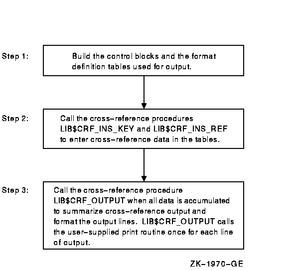
Using the cross-reference routines involves the following steps:

  1. Define a table of control information, using the $CRFCTLTABLE macro.
  2. Define each field of the output line, using the $CRFFIELD macro.
  3. Specify the end of each set of macros that define a field in the output line, using the $CRFFIELDEND macro.
  4. Provide data by calling one of the two following cross-reference entry points:
    • LIB$CRF_INS_KEY inserts an entry for the specified key in the specified symbol table.
    • LIB$CRF_INS_REF inserts a reference to a key in the specified symbol table.
  5. Call LIB$CRF_OUTPUT, the cross-reference output routine, to summarize and format the data.
  6. Supply a routine that the output routine calls to print each line in the output file. Because you supply this routine, you can control the number of lines per page and the header lines.

Figure 25-1 illustrates the steps required in using the cross-reference routines.

Figure 25-1 Using Cross-Reference Routines

The Run-Time Library provides three macros to initialize the data structures used by the cross-reference routines:

  1. $CRFCTLTABLE defines a table of control information.
  2. $CRFFIELD defines each field of the output format definition table. Multiple $CRFFIELD macro instructions can be issued in defining one particular field.
  3. $CRFFIELDEND ends a set of $CRFFIELD macro instructions (a format table).

25.2 $CRFCTLTABLE Macro

$CRFCTLTABLE initializes a cross-reference control table. Your program must issue one $CRFCTLTABLE macro for each cross-reference table you build. You can accumulate information for more than one cross-reference table at a time. For this reason, you must define a table for each set of cross-references, and include the address of that table each time you call a cross-reference routine to insert data.

The $CRFCTLTABLE macro instruction has the following format:


label: $CRFCTLTABLE keytype, output, error, memexp, key1table,
                    key2table, val1table, val2table,
                    ref1table, ref2table

label

The address of the control table. You must specify a control table address in all calls to the cross-reference routines.

keytype

The type of key to enter into the table. The following key types are defined:
ASCIC Keys are counted ASCII strings, with a maximum of 31 characters (symbol name).
BIN_U32 Keys are 32-bit unsigned binary values. The binary-to-ASCII conversion is done by $FAO using the format string for the KEY1 field.

output

The address of the routine that you supply to print a formatted output line. The output line is passed to the output routine by descriptor.

error

The address of an error routine to execute if the called cross-reference routine encounters an error. The error code (longword) is passed to the error routine by value. In other words, it is a copy of the constant on the stack. A value of zero indicates that no error routine is supplied.

memexp

The number of pages by which to expand region when needed. The default is 50.

key1table

The address of the field descriptor table for the KEY1 field. A value of zero indicates that the field is not to be included in the output line.

The remaining arguments provide the address of the field descriptor tables for the KEY2, VAL1, VAL2, REF1, and REF2 fields, respectively, of the output line. You can use these argument names as keywords in the macros. For example, you can use KEYTYPE as a keyword when issuing the $CRFCTLTABLE macro.

25.3 $CRFFIELD Macro

For each field in the output line, you must issue a $CRFFIELD instruction to identify the field, supply an $FAO command string to control the printing of the field, and provide flag information. See the program example and the description of $FAO (formatted ASCII output) in the OpenVMS System Services Reference Manual. The $CRFFIELD macro has the following format:


label: $CRFFIELD bit_mask, fao_string, field_width, set_clear

label

The address of the field descriptor table generated as a result of this set of $CRFFIELD macro instructions. The label field can be omitted after the first macro of the set. These addresses correspond to the field descriptor table addresses in the $CRFCTLTABLE macro.

bit_mask

A 16-bit mask. When the user enters a key or reference, the cross-reference routine stores flag information with the entry. When preparing the output line, LIB$CRF_OUTPUT performs an AND operation on the 16-bit mask in the field descriptor table with the flag stored with the entry. Any number of bit masks can be defined for a field. $CRFFIELD macro instructions are used to define multiple bit patterns for a flag field. The high-order bit is reserved to the cross-reference routines.

fao_string

The $FAO command string. LIB$CRF_OUTPUT uses this string to determine the $FAO format when formatting this field for output.

field_width

The maximum width of the output field.

set_clear

The indicator used to determine whether the bit mask is to be tested as set or clear when determining which flag to use. SET indicates test for set; CLEAR indicates test for clear.

You can use the argument names shown here as keywords in your program.

In the following example, one bit pattern is defined twice; once indicating a string that is to be printed if the pattern is set, and once indicating that spaces are to appear if the pattern is clear.


$CRFFIELD       BIT_MASK=SYM$M_REL, FAO_STRING=3_\##_\,-
                SET_CLEAR=CLEAR, FIELD_WIDTH=2
$CRFFIELD       BIT_MASK=SYM$M_REL, FAO_STRING=_\-R_\,-
                SET_CLEAR=SET, FIELD_WIDTH=2

If more than one set of flags is defined for a field, each FAO string must print the same number of characters; otherwise, the output is not aligned in columns.

The fields for the symbol name, symbol value, and references are always formatted using the first descriptor in the corresponding table.

25.4 $CRFFIELDEND Macro

The $CRFFIELDEND macro instruction marks the end of a set of macros that describe one field of the output line. It is used once to end each set of field descriptors. It has the following format:


$CRFFIELDEND

25.5 Cross-Reference Output

LIB$CRF_OUTPUT can format output lines for three types of cross-reference listings:

  1. A summary of symbol names and their values, as illustrated in Figure 25-2.
  2. A summary of symbol names, their values, and the names of modules that refer to the symbol, as illustrated in Figure 25-3.
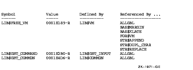
  3. A summary of symbol names, their values, the name of the defining module, and the names of those modules that refer to the symbol, as illustrated in Figure 25-4.

Figure 25-2 Summary of Symbol Names and Values
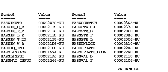

Figure 25-3 Summary of Symbol Names, Values, and Name of Referring Modules
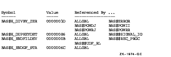

Figure 25-4 Summary Indicating Defining Module

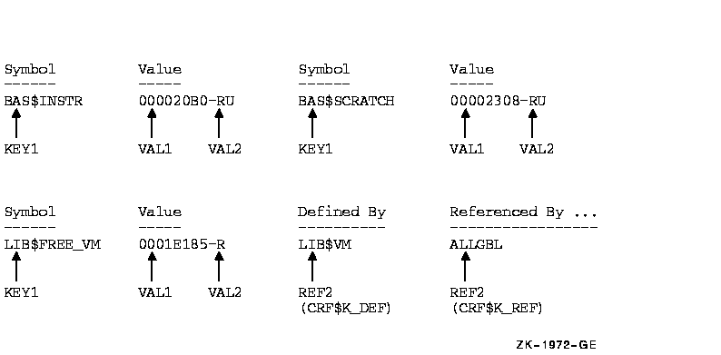
Regardless of the format of the output, LIB$CRF_OUTPUT considers the output line to consist of the following six different field types:

  1. KEY1 is the first field in the line. It contains a symbol name.
  2. KEY2 is the second field in the line. It contains a set of flags (for example,--R) providing information about the symbol.
  3. VAL1 is the third field in the line. It contains the value of the symbol.
  4. VAL2 is the fourth field in the line. It contains a set of flags describing VAL1.
  5. REF1 and REF2 fields. Within each REF1 and REF2 pair, REF1 provides a set of flags and REF2 provides the name of a module that references the symbol.

Figure 25-5 shows that any of these fields can be omitted from the output.

Figure 25-5 Output Line for LIB$CRF_OUTPUT

25.6 Example

The VAX Linker uses the cross-reference routines to generate cross-reference listings. This section uses the linker's code as an example of using the cross-reference routines in a MACRO program.

25.6.1 Defining Control Tables

Cross-reference routines use two control tables:

  • The symbol-by-name table
  • The symbol-by-value table

First, the linker uses the $CRFCTLTABLE macro to set up the characteristics and fields of the symbol-by-name table. This table will list symbols by name and provide a cross-reference synopsis. The table is set up as follows:


LNK$NAMTAB:
            $CRFCTLTABLE   KEYTYPE=ASCIC,ERROR=LNK$ERR_RTN,_
                           OUTPUT=LNK$MAPOUT,KEY1TABLE=LNK$KEY1,_
                           KEY2TABLE=LNK$KEY2,VAL1TABLE=LNK$VAL1,_
                           VAL2TABLE=LNK$VAL2,REF1TABLE=LNK$REF1,_
                           REF2TABLE=LNK$REF2
LNK$NAMTAB Names the address of the control table
KEYTYPE=ASCIC Specifies that the keys are counted ASCII strings (that is, symbol names)
ERROR=LNK$ERR_RTN Indicates that LNK$ERR_RTN is the address of the routine to be executed in case of error
OUTPUT=LNK$MAPOUT Names LNK$MAPOUT as the address of the user-supplied routine that prints the formatted table

The remaining arguments provide the addresses of the field descriptor tables.

After setting up the control tables, the linker defines each field of the cross-reference output line, using the $CRFFIELD macro. After each set of definitions for a field, it calls $CRFFIELDEND to mark the end of the field.

Note particularly the following two features of this set of definitions:

  • The definition of LNK$VAL2 describes a flag to be associated with VAL1. The definition contains alternative bit patterns, depending on the bit mask. When an entry is made to the table, the entry contains flag information. Then, when LIB$CRF_OUTPUT is called to format the data, the routine checks each entry, matching the flags argument against the bit masks specified in the control table. When LIB$CRF_OUTPUT finds a match, it uses that definition to determine the format of the entry in the output table. For example, BIT_MASK=SYM$M_DEF marks an entry as the defining reference. The corresponding VAL1 entry is placed in the output table with an asterisk in its flags field.
  • The FAO control strings are defined to produce an output of the maximum character size for each field. This ensures that the columns will line up correctly in the output. For example, !15AC produces the variable symbol name left-aligned and right-filled with spaces. Another example is the three sets of characters to be printed for field VAL2. Each FAO control string produces two characters, which is the maximum size of the field.


LNK$KEY1:
            $CRFFIELD      BIT_MASK=0, FAO_STRING=\!15AC\,-
                           SET_CLEAR=SET,FIELD_WIDTH=15
            $CRFFIELDEND
LNK$KEY2:
            $CRFFIELD      BIT_MASK=0,FAO_STRING=\ \,-
                           SET_CLEAR=SET, FIELD_WIDTH=1
            $CRFFIELDEND

LNK$VAL1:
            $CRFFIELD      BIT_MASK=0,FAO_STRING=\!XL\,-
                           SET_CLEAR=SET,FIELD_WIDTH=8
            $CRFFIELDEND
LNK$VAL2:
            $CRFFIELD      BIT_MASK=0, FAO_STRING=\!2*  \,-
                           SET_CLEAR=SET,FIELD_WIDTH=2
            $CRFFIELD      BIT_MASK=SYM$M_REL,FAO_STRING=\-R\,-
                           SET_CLEAR=SET,FIELD_WIDTH=2
            $CRFFIELD      BIT_MASK=SYM$M_DEF, FAO_STRING=\-*\,-
                           SET_CLEAR=CLEAR,FIELD_WIDTH=2
            $CRFFIELDEND
LNK$REF1:
            $CRFFIELD      BIT_MASK=0,FAO_STRING=\!6* \,-
                           SET_CLEAR=SET,FIELD_WIDTH=6
            $CRFFIELD      BIT_MASK=SYM$M_WEAK,FAO_STRING=\!3* WK-\,-
                           SET_CLEAR=SET,FIELD_WIDTH=6
            $CRFFIELDEND

LNK$REF2:
            $CRFFIELD      BIT_MASK=0,FAO_STRING=\!16AC\,-
                           SET_CLEAR=SET,FIELD_WIDTH=16
            $CRFFIELDEND

After initializing the symbol-by-name table, the linker sets up a second control table. This table defines the output for a symbol-by-value synopsis. For this output, the value fields are eliminated. The symbols having this value are entered as reference indicators. None is specified as the defining reference. The control table uses the field descriptors set up previously. The following macro instructions are used:


LNK$VALTAB:
            $CRFCTLTABLE    KEYTYPE=BIN_U32, ERROR=LNK$ERR_RTN,-
                            OUTPUT=LNK$MAPOUT,KEY1TABLE=LNK$VAL1,-
                            KEY2TABLE=LNK$VAL2,VAL1TABLE=0,-
                            VAL2TABLE=0,REF1TABLE=LNK$REF1,-
                            REF2TABLE=LNK$REF2


Previous Next Contents Index