Software > OpenVMS Systems > Documentation > 732final > 6318 HP OpenVMS Systems Documentation |
Guidelines for OpenVMS Cluster Configurations
6.3 HSx Failover ModesThe HSZ70, HSZ80, and HSGx implement two modes of failover operation when they are in a dual-redundant configuration, transparent failover mode, and multibus failover mode. HSVx supports multibus failover only.
For the system to operate correctly, the HSx failover mode must be compatible with the configuration of the interconnect hardware and the host operating system software, as described in the following sections. 6.3.1 Transparent Failover ModeIn transparent failover mode, the HSx presents each logical unit on one port of the dual controller pair. Different logical units may be assigned to different ports, but an individual logical unit is accessible through one port at a time. As shown in Figure 6-4, when the HSZ detects that a controller module has failed, it moves the logical unit to the corresponding port on the surviving controller. Figure 6-4 Storage Subsystem in Transparent Mode 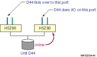
The assumption in transparent mode is that the two ports are on the same host bus, so the logical unit can move from one port to the other without requiring any changes to the host's view of the device. The system manager must ensure that the bus configuration is correct for this mode of failover. OpenVMS has supported transparent failover for HSZ controllers since Version 6.2. To select transparent failover mode on the HSZ or HSG, enter one of the following commands at the console, depending on your configuration:
or
An example of the output of a console SHOW command on an HSZ in transparent mode follows:
6.3.2 Multibus Failover Mode (Disks Only)In multibus failover mode, the HSx responds to SCSI Inquiry commands from the host on all ports of the dual controller pair. This allows the host to be aware of all the possible paths to the device. There are two advantages to having the host aware of all the paths to a device:
Note that, although the logical unit is visible on all ports, it is on line and thus capable of doing I/O on the ports of only one controller at a time. Different logical units may be on line to different controllers, but an individual logical unit is on line to only one controller at a time, as shown in Figure 6-5. Figure 6-5 Storage Subsystem in Multibus Mode 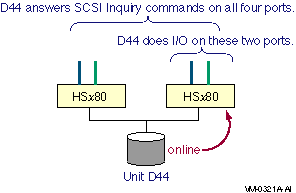
You can determine which controller a logical unit is on line to by entering the HSx console command, as follows:
The host executes I/O to a logical unit on one path at a time, until that path fails. If a controller has two ports, as the HSZ80 and the HSG80 controllers do, then different hosts can access the same logical unit over different ports of the controller to which the logical unit is on line. An HSx in multibus failover mode can only be used with the multipath functionality introduced in OpenVMS Version 7.2. To select multibus failover mode, enter one of the following commands at the HSx: console, whichever is appropriate to your configuration:
or
An example of the output of a console SHOW command on an HSx controller in multibus mode follows:
6.3.3 Port Addressing for Controllers in Multibus ModeThere is a difference between parallel SCSI and FC in the way that the ports on multibus controllers are addressed. In parallel SCSI (the HSZ70 and the HSZ80), all the ports are assigned the same SCSI target IDs. This is noted for the HSZ80 configuration shown in Figure 6-6. Figure 6-6 Port Addressing for Parallel SCSI Controllers in Multibus Mode 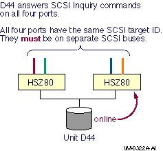
The reason all the ports have the same target ID is that the target ID is part of the OpenVMS device name (for example, the 6 in $4$DKC600), and the device name must be the same for all paths. This means that each port must be on a separate SCSI bus or there will be an address conflict. In Fibre Channel configurations with the HSGx or the HSVx, all the ports have their own FC address and WWID, as noted in Figure 6-7. The same is true for the MDR. Figure 6-7 Port Addressing for Fibre Channel Controllers in Multibus Mode 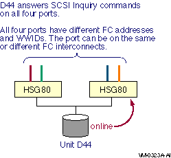
The ports on the HSGx and the HSVx have separate FC addresses and WWIDs because these items are not used in the OpenVMS FC device name. This means that any number of ports can be connected to the same FC interconnect. In fact, all the ports of the HSGx or HSVx in multibus mode should be connected, even if there is just one interconnect, because this can improve availability and performance. 6.4 Parallel SCSI Multipath Configurations (Disks Only)The figures in this section show systems configured for transparent failover and for multipath failover. The special considerations for controller modules that have multiple ports, such as the HSZ80, are also described. 6.4.1 Transparent FailoverTransparent failover in a parallel SCSI configuration, as shown in Figure 6-8, requires that both controller modules be on the same SCSI bus. Figure 6-8 Parallel SCSI Configuration With Transparent Failover 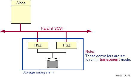
In this configuration:
6.4.2 Multibus Failover and Multiple PathsA parallel SCSI configuration with multiple paths from the host to storage offers higher availability and performance than a configuration using transparent failover. Figure 6-9 shows this configuration. Figure 6-9 Parallel SCSI Configuration With Multibus Failover and Multiple Paths 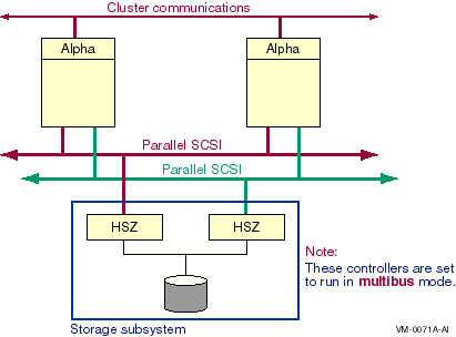
Note the following about this configuration:
6.4.3 Configurations Using Multiported Storage ControllersHigher levels of availability and performance can be achieved with the use of multiported storage controllers, such as the HSZ80. The HSZ80 storage controller is similar to the HSZ70 except that each HSZ80 controller has two ports. This section shows three configurations that use multiported storage controllers. The configurations are presented in order of increasing availability. Figure 6-10 shows a single host with a single interconnect, using an HSZ80 in transparent mode. Figure 6-10 Multiported Parallel SCSI Configuration With Single Interconnect in Transparent Mode 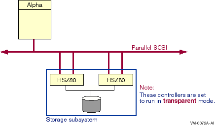
Note the following about this configuration:
Figure 6-11 shows a system configured in transparent mode using two paths from the host. Figure 6-11 Multiported Parallel SCSI Configuration With Multiple Paths in Transparent Mode 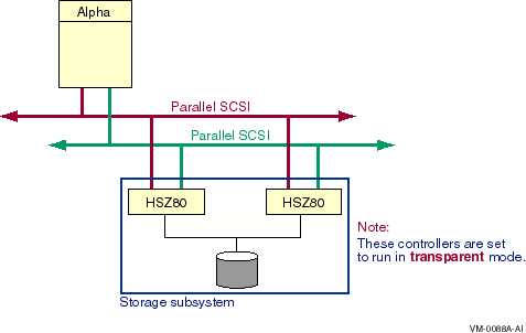
In this configuration:
Note that in this configuration, although there are two buses, there is only one path from the host to a particular logical unit. When a controller fails, the logical unit moves to the corresponding port on the other controller. Both ports are on the same host bus. This configuration has better performance than the one in Figure 6-10 because both SCSI buses can be simultaneously active. This configuration does not have higher availability, however, because there is still only one path from the host to the logical unit. Figure 6-12 shows a system using the multiported HSZ80 storage controller configured in multibus mode. Figure 6-12 Multiported Parallel SCSI Configuration With Multiple Paths in Multibus Mode 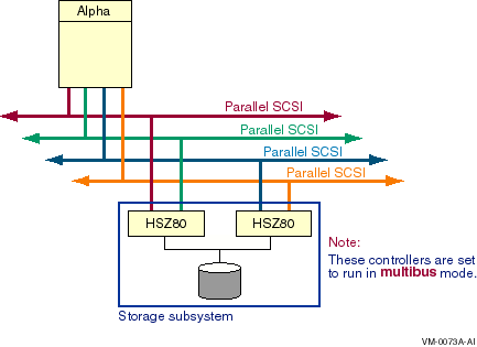
In this configuration:
6.5 Disk Device Naming for Parallel SCSI Multipath ConfigurationsSCSI device names have evolved as systems have become larger and more complex. At first, SCSI device names were entirely path dependent. The device name indicated the node, host adapter, SCSI bus ID, and logical unit number (LUN) used to access the device. Path-based names are not suitable for multiple host and multiple path environments because:
The first two of these issues were addressed by the use of the node allocation class and the port allocation class. The third issue requires the introduction of an HSZ controller-based allocation class. These three allocation classes are reviewed in the following sections. 6.5.1 Review of Node Allocation ClassesA node allocation class is used in a device name in place of a node name. A node allocation class is needed to produce a unique device name when multiple nodes have a direct connection to the same SCSI device. A node allocation class can only be used in a device name when all nodes that share access to a SCSI storage device:
Figure 6-13 shows a configuration whose devices are named using a node allocation class. Figure 6-13 Devices Named Using a Node Allocation Class 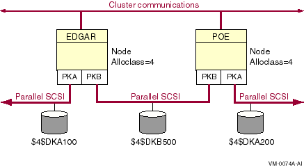
6.5.2 Review of Port Allocation ClassesA port allocation class in a device name designates the host adapter that is used to access the device. The port allocation class replaces the node allocation class in the device name, and the adapter controller letter is set to the constant A. The port allocation class can be used when SCSI systems need more SCSI IDs to produce unique device names, or when the controller letter of the adapters on a shared bus do not match. A port allocation class can only be used in a device name when all nodes that share access to a SCSI storage device have only one direct path to the device. Figure 6-14 shows a configuration whose devices are named using a port allocation class. Figure 6-14 Devices Named Using a Port Allocation Class 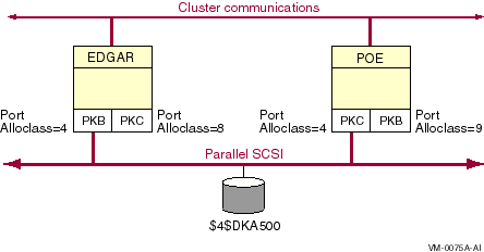
6.5.3 Device Naming Using HSZ Allocation ClassesWhen any node has multiple buses connecting to the same storage device, the new HSZ allocation class shown in Figure 6-15 must be used. Figure 6-15 Devices Named Using an HSZ Allocation Class 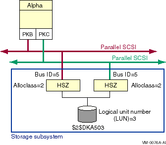
An HSZ allocation class is similar to the HSC, HSD, and HSJ allocation classes. The device name, using an HSZ allocation class number, takes the following form:
where:
The system manager sets an HSZ allocation class from the HSZ console, using one of the following commands, as appropriate to the configuration:
or
where n is a value from 1 to 999. When the allocation class is set on one controller module in a dual redundant configuration, it is automatically set to the same value on the other controller. In the following example, the allocation class is set to 199. The example shows that the value is set for both controllers.
The following rules pertain to the use of an HSZ allocation class in SCSI device names:
6.6 Fibre Channel Multipath ConfigurationsFigure 6-16 shows a multipath configuration with both a tape storage subsystem and a disk storage subsystem. Note that the disk storage controllers are configured in multibus mode. Figure 6-16 Single Host With Two Dual-Ported Storage Controllers, One Dual-Ported MDR, and Two Buses 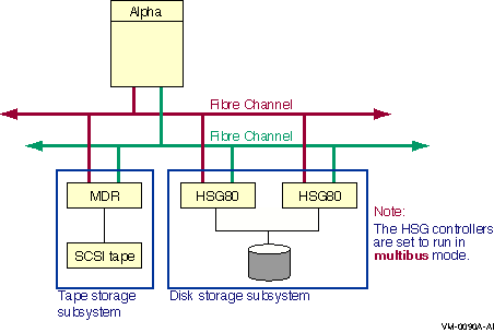
Note the following about this configuration:
Note that each HSG80 port has its own Fibre Channel address and Fibre Channel port WWID. This is different from an HSZ80 in multibus mode where all the ports respond to the same SCSI address and must, therefore, be connected to different SCSI buses. The separate FC addresses enable both ports of the dual HSG80 to be on the same FC. Figure 6-17 is similar to Figure 6-16, except it has two additional Fibre Channel interconnects. Figure 6-17 Single Host With Two Dual-Ported Storage Controllers, One Dual-Ported MDR, and Four Buses 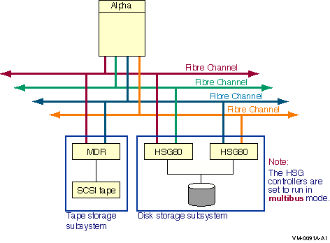
Note the following about this configuration:
Figure 6-18 builds on the previous two figures. Instead of a single host, it has two hosts. Figure 6-18 Two Hosts With Two Dual-Ported Storage Controllers, One Dual-Ported MDR, and Four Buses 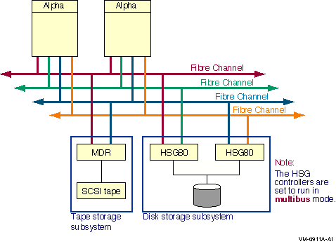
Note the following about this configuration:
6.7 Implementing Multipath ConfigurationsParallel SCSI and Fibre Channel interconnects support multipath configurations. Implementation of these configurations is similar, and the system parameters and the command for specifying paths are the same. The syntax for the path identifiers differs. Implementing multiple paths to devices consists of the following steps:
|