Software > OpenVMS Systems > Documentation > 82final > 5973 HP OpenVMS Systems Documentation |
HP OpenVMS Calling Standard
4.7.5.3 Argument Information (AI) RegisterIn addition to the normal parameters, an implicit argument information value is passed in register R25, the Argument Information (AI) register. This value is shown in Figure 4-6. Figure 4-6 Argument Information Register Representation 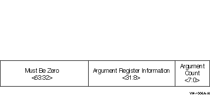
Argument Count is an unsigned byte that specifies the number of 64-bit argument slots used for the argument list. (Note that single and double-precision complex values use two slots, which is reflected in this count.) Argument Register Information is a contiguous group of eight 3-bit fields that correspond to the eight arguments passed in registers. The first group, bits <10:8>, describes the first argument, the second group, bits <13:11>, describes the second argument, and so on. The encoding for each group is described in Table 4-12.
4.7.5.4 Memory Stack ParametersThe remainder of the parameter list, beginning with slot 8, is passed in the outgoing parameter area of the memory stack frame, as described in Section 4.5.1. Parameters are mapped directly to memory, with slot 8 placed at location SP+16, slot 9 placed at location SP+24, and so on. Each argument is stored in memory as a series of one or more 64-bit storage units, with unused bits in the last unit undefined. 4.7.5.5 Variable Argument ListsThe rules above support variable-argument list functions in both the K&R and the ANSI dialects of the C language. (Note that argument location is independent of whether a prototype is in scope.) The nth argument is in either Rn or Fn regardless of the type of parameter in the preceding register slot. Therefore, a function with variable arguments may assume that the variable arguments that lie within the first eight argument slots can be found in either the stacked input integer registers (IN0-IN7), or in the floating-point parameter registers (F8-F15). Using the information codes from the the AI (Argument Information) register (see Table 4-12), the function can then store these registers to memory using the 16-byte scratch area for IN6/F14 and IN7/F15, and up to 48 bytes at the base of its own stack frame for IN0/F8-IN5/F13, as necessary. This arrangement places all of the variable parameters in one contiguous block of memory. 4.7.5.6 Pointers to Formal ParametersWhenever the address is formed of a formal parameter that is passed in a register, the compiler must store the parameter to the stack, as it would for a variable argument list. 4.7.5.7 Languages Other than CThe placement of arguments in general registers versus floating-point registers does not depend on any notion or concept of a prototype being in scope. It is therefore applicable to all languages at all times. 4.7.5.8 Rounding Floating-point ValuesThere must be no difference in behavior between a floating-point parameter passed directly in a register and a floating-point parameter that has been stored to memory and reloaded. In either case, the floating-point value must be the same. This implies that floating-point parameters passed in floating-point registers must be explicitly rounded to the proper precision by the caller. 4.7.5.9 Order of Argument EvaluationBecause most high-level languages do not specify the order of evaluation (with respect to side effects) of arguments, those language processors can evaluate arguments in any convenient order. The choice of argument evaluation order and code generation strategy is constrained only by the definition of the particular language. Programs should not depend on the order of evaluation of arguments. 4.7.5.10 ExamplesThe following examples illustrate the parameter passing conventions. Floating-point types are IEEE floating-point representations.
Scalar Integers and Floats, With or Without Prototype
The parameters are passed as follows:
No padding is provided in the parameter list for the structure (independent of its external alignment). The parameters are passed as follows:
The parameters are passed as follows:
Floating-Point Aggregates, With or Without Prototype
The parameters are passed as follows:
4.7.6 Return ValuesValues up to 128 bits are returned directly in the registers, according to the rules in Table 4-13. Integer, enumeration, record, and set values (bit vectors) smaller than 64 bits must be zero-filled (unsigned integers, enumerations, records, sets) or sign-extended (signed integrals) to a full 64 bits. However, for unsigned 32-bit integers, bit 31 is replicated in bits 32--63. When floating-point values are returned in floating-point registers, they are returned in the register format, rounded to the appropriate precision. When they are returned in the general registers (for example, as part of a record), they are returned in their memory format. OpenVMS does not support a general notion of homogeneous floating-point aggregates. However, the special case of two single-precision or double-precision floating-point values implementing values of a complex type are handled in an analogous manner.
The rules in Table 4-13 are expressed in more detail in Table 4-10. F_floating and F_floating complex values in the general registers are zero-extended (Zero64), because this most closely approximates the effect of using the Alpha register format. Return values other than those covered by Table 4-13 are returned in a buffer allocated by the caller. A pointer to the buffer is passed to the called procedure as a hidden first parameter, and all normal parameters are shifted one slot to make this possible. The return buffer must be aligned at a 16-byte boundary. 4.7.7 Simple and Bound ProceduresThere are two distinct classes of procedures:
A simple procedure is a procedure that does not need direct access to the stack of its execution environment. In order to call a simple procedure, a simple function descriptor is created, as shown in Figure 4-7, and described in Table 4-14. Figure 4-7 Simple Function Descriptor 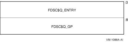
A bound procedure is a procedure that does need direct access to the stack of its execution environment, typically to reference an up-level variable or to perform a nonlocal GOTO operation. When a bound procedure is called, the caller must pass some kind of pointer to the called code that allows it to reference its up-level environment. Typically, this pointer is a frame pointer for that environment, but many variations are possible. When the caller itself is executing within that outer environment, it can usually make such a call directly to the code for the nested procedure without recourse to any additional function descriptors. However, when a procedure value for the nested procedure must be passed outside of that environment to a call site that has no knowledge of the target procedure, a bound function descriptor is created so that the nested procedure can be called just like a simple procedure. Bound procedure values, as defined by this standard, are designed for multilanguage use and utilize the properties of function descriptors to allow callers of procedures to use common code to call both bound and simple procedures. A bound function descriptor is similar to a simple function descriptor, with several additional fields as shown in Figure 4-8 and described in Table 4-15. Figure 4-8 Bound Function Descriptor 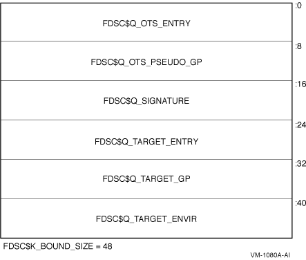
A bound procedure descriptor is inherently dynamic because the environment value must be determined at runtime by code executing within the bound procedure environment. Therefore, when a bound procedure descriptor such as this is needed, it is usually allocated on the creating procedure's stack. When a procedure value that refers to a bound procedure descriptor is used to make a call, the routine designated in the OTS_ENTRY field (typically OTS$JUMP_TO_BPV) receives control with the GP register pointing to the bound procedure descriptor (instead of a global offset table). This routine performs the following steps:
Control arrives at the real target procedure address with both the GP and environment register values established appropriately. Support routine OTS$JUMP_TO_BPV is included as a standard library routine. The operation of OTS$JUMP_TO_BPV is logically equivalent to the following code:
Because the address of a bound function descriptor is a valid function pointer, it may be passed to translated code which uses it to call back into native code; therefore, the value of the signature information field must be the same as that in the official function descriptor for the real target procedure (see Section 5.1.2). Note that there can be multiple OTS$JUMP_TO_BPV-like support routines, corresponding to different target registers where the environment value should be placed. The code that creates the bound function descriptor is also necessarily compiled by the same compiler that compiles the target procedure, thus can correctly select an appropriate support routine. 4.8 Procedure Call StackA procedure is an active procedure while its body is executing, including while any procedure it calls is executing. When a procedure is active, its designated condition handler may handle an exception that is signaled during its execution. Associated with each active procedure is an invocation context, informally called a frame, which consists of the set of registers and space in memory that is allocated and that may be accessed during execution for a particular call of that procedure. When a procedure begins to execute, it has a limited invocation context that includes the output registers of its caller (which have been "shifted" to start at register R32). The initial instructions may allocate and initialize additional context, including possibly saving information from the invocation context of its caller. Such instructions, if any, are termed a procedure prologue. Once execution of the prologue is complete, the procedure is said to be active. When a procedure is ready to return to its caller, the instructions that deallocate and discard the procedure's invocation context (which may include restoring state of the caller's invocation context that was saved during the prologue), are termed a procedure epilogue. A null frame procedure has no prologue and no epilogue, and consists solely of body instructions. Such a procedure becomes active immediately. A procedure may have more than one prologue if there are multiple entry points. A procedure may also have more than one epilogue if there are multiple return points. One of each will be executed during any given invocation of the procedure. A procedure call stack (for a thread) consists of the stack of invocation contexts that exists at any point in time. New invocation contexts are pushed on that stack as procedures are called and invocations are popped from the call stack as procedures return. The invocation context of a procedure that calls another procedure is said to precede or be previous to the invocation context of the called procedure. 4.8.1 Current ProcedureThe current procedure is the active procedure whose execution began most recently; its invocation context is at the top of the call stack. Note that a procedure executing in its prologue or epilogue is not active, and hence cannot be the current procedure. For OpenVMS, the PC (instruction pointer) register in combination with associated unwind information determines what procedure is current (for exception handling purposes). See Section A.4 for a description of the unwind information data structures. A procedure is current at a given PC (when OpenVMS semantics apply, see Section A.4.1) if either:
4.8.2 Procedure Call TracingMechanisms for each of the following functions are needed to support procedure call tracing:
This section describes the data structure mechanisms. The run-time library functions that support these functions are described in Section 4.8.3
|