Software > OpenVMS Systems > Documentation > 82final > 5973 HP OpenVMS Systems Documentation |
HP OpenVMS Calling Standard
A.4.3.1 General Information SegmentThe OpenVMS general information segment contains various flags and general exception handling information, and is described in Table A-14. A general information segment may be omitted if all of its fields would have their default values. If a general information segment is present, it must be the first segment in the operating system-specific data area.
1This is different than on Alpha, where a stack search is performed even when no floating-point exceptions are enabled in the Alpha FPCR (see the description of PDSC$V_EXCEPTION_MODE in Table 3-3 and Table 3-4.) A.4.3.2 Caller Spill Register InformationThe OpenVMS caller spill register information segment encodes information to emulate the effects of callee register saving conventions even when caller save/restore conventions are in use. The key difference between this and the more general unwind information described in other parts of Section A.4 is that the information described here must be applied in the frame with which it is associated in order to complete that frame whereas other information is applied in order to unwind to the previous frame. The caller spill register segment is described in Table A-15.
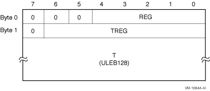
The OSSD$T_SPILL_DATA field in a spill register segment consists of a sequence of triples encoded as shown in Figure A-3. Figure A-3 Format of OSSD$T_SPILL_DATA 
Table A-16 describes the fields in the OSSD$T_SPILL_DATA segment.
It is valid for two or more save actions for the same register REG to occur without an intervening restore of that register. In this case, the later save register location TREG supercedes the earlier one as the save location for register REG beginning at the specified offset T. When unwinding to a frame, the unwind information of the called frame is first used to construct the frame of the caller; the unwind operation must then be completed by using any spill register information for that caller. A.4.4 Language-Specific Data AreaThe language-specific data area contains information whose format and interpretation need be known only by the condition handler that uses it. As such, this area is not described in this document. To preserve sharability of the image of which language-specific data is a part, that data should be read-only and position-independent. For example, an address within the associated procedure might be represented as an offset relative to the starting address given in the unwind table for the routine. The following fields, which are found in the mechanism vector passed to a condition handler (see Sections 8.5.1 and 8.5.1.2.3), may be helpful in interpreting the contents of language-specific data:
A.5 Default Unwind InformationA null frame procedure may have no corresponding unwind table entry, hence no unwind information block, if all of the following apply:
Such a procedure is necessarily a leaf procedure, that is, a procedure that makes no calls, either explicitly or implicitly. (To make a call, a procedure must preserve at least B0 and AR.PFS.) Conversely, if the dispatcher or unwinder encounters a PC for the top-most procedure on the call stack that is not represented in the unwind tables, it assumes that the PC corresponds to a null frame leaf procedure that satisfies the properties described above. A.6 System Unwind RoutinesSee the HP OpenVMS System Services Reference Manual for descriptions of the following unwind routines:
See the HP OpenVMS RTL Library (LIB$) Manual for a decription of the following routine:
Appendix B
|
|||||||||||||||||||||||||||||||||||||||||||||||||||||||||||||||||||||||||||||||||||||||||||||||||||||||||||||||||||||||||||||||||||||||||||||||||||||||||||||||||||||||||||||||||||||||||||||||||||||||||||||||||||||||||||||||||||||||||
For compatibility with the VAX and Alpha calling standards, this appendix describes big-endian values stored in little-endian bytes. |
The unwind descriptor records are encoded in variable-length byte strings. The various record formats are described in this appendix. The first byte of each record is sufficient to determine its format. The high-order bit of this byte determines whether it is a header record (if the bit is zero), or a region descriptor record (if the bit is one). The remaining bits and any subsequent bytes are divided into separate fields. In most formats, the first field, R, identifies the record type. The record formats are listed by the bit pattern of the first byte in Table B-1.
| Region Header Records | Prologue Descriptor Records | Body Descriptor Records | |||
|---|---|---|---|---|---|
| Bit Pattern | Format | Bit Pattern | Format | Bit Pattern | Format |
| 00-- ---- | R1 | 100- ---- | P1 | 10-- ---- | B1 |
| 0100 0--- | R2 | 1010 ---- | P2 | ||
| 0110 00-- | R3 | 1011 0--- | P3 | ||
| 1011 1000 | P4 | ||||
| 1011 1001 | P5 | ||||
| 110- ---- | P6 | 110- ---- | B2 | ||
| 1110 ---- | P7 | 1110 0000 | B3 | ||
| 1111 0000 | P8 | 1111 -000 | B4 | ||
| 1111 0001 | P9 | ||||
| 1111 1001 | X1 | 1111 1001 | X1 | ||
| 1111 1010 | X2 | 1111 1010 | X2 | ||
| 1111 1011 | X3 | 1111 1011 | X3 | ||
| 1111 1100 | X4 | 1111 1100 | X4 | ||
| 1111 1111 | P10 | ||||
Some fields in the unwind descriptor records are variable in length. The variable-length encoding uses the ULEB128 (Unsigned Little-Endian Base 128) encoding, described below:
Table B-2 shows example ULEB128 encodings.
| Value | Encoding | Interpretation |
|---|---|---|
| 0 | 00000000 | 0 |
| 127 | 01111111 | 127 |
| 128 |
10000000
00000001 |
0 + (1 << 7) |
| 1544 |
10001000
00001100 |
8 + (12 << 7) |
| 49,802 |
10001010
10000101 00000011 |
10 + (5 << 7) + (3 << 14) |
Fields in the ULEB128 format always follow the fixed fields, and begin on a byte boundary.
The PROLOGUE and BODY region header records can appear in either format R1 or R3, depending on the magnitude of the region length field. If the region length is no greater than 31 instruction slots, the R1 format may be used; otherwise, format R3 must be used.

This format is used for the short forms of the PROLOGUE and BODY region header records. The R bit identifies the record type, as shown in the following table:
| Record Type | R |
|---|---|
| PROLOGUE | 0 |
| BODY | 1 |

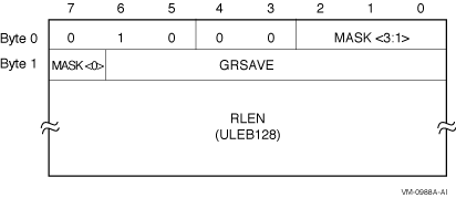
This format is used only for the PROLOGUE_GR region header record. The following table shows the meaning of the bits in the MASK field:
| Mask bit | Meaning when bit is set |
|---|---|
| Byte 0, bit 2 | RP is saved in a standard general register. |
| Byte 0, bit 1 | AR.PFS is saved in a standard general register. |
| Byte 0, bit 0 | PSP is saved in a standard general register. |
| Byte 1, bit 7 | Predicate registers are saved in a standard general register. |
The GRSAVE field identifies the general register in which the first of these values is stored. Additional general registers are used as needed. For example, assume that RP, AR.PFS, and the predicate registers are stored, but not PSP. The mask bits would be 1101, and GRSAVE might be set to 39, indicating that the three values are stored in R39, R40, and R41, respectively.
| Previous | Next | Contents | Index |