Software > OpenVMS Systems > Documentation > 82final > 6318 HP OpenVMS Systems Documentation |
Guidelines for OpenVMS Cluster Configurations
Chapter 7
|
The Fibre Channel interconnect is shown generically in the figures in this chapter. It is represented as a horizontal line to which the node and storage subsystems are connected. Physically, the Fibre Channel interconnect is always radially wired from a switch, as shown in Figure 7-1. The representation of multiple SCSI disks and SCSI buses in a storage subsystem is also simplified. The multiple disks and SCSI buses, which one or more HSGx controllers serve as a logical unit to a host, are shown in the figures as a single logical unit. For ease of reference, the term HSG, which represents a Fibre Channel hierarchical storage controller, is used throughout this chapter to represent both an HSG60 and an HSG80, except where it is important to note any difference, as in Table 7-2. |
Fibre Channel is an ANSI standard network and storage interconnect that offers many advantages over other interconnects. Its most important features and the support offered by OpenVMS for these features are shown in Table 7-1.
| Feature | OpenVMS Support |
|---|---|
| High-speed transmission | OpenVMS supports 2 Gb/s, full-duplex, serial interconnect (can simultaneously transmit and receive 200 MB of data per second). |
| Choice of media | OpenVMS supports fiber-optic media. |
| Long interconnect distances | OpenVMS supports multimode fiber-optic media at 500 meters per link and single-mode fiber-optic media (for interswitch links [ISLs]) for distances up to 100 kilometers per link. |
| Multiple protocols | OpenVMS supports SCSI--3. Possible future support for IP. |
| Numerous topologies | OpenVMS supports switched FC (highly scalable, multiple concurrent communications) and multiple switches (fabric). Support is planned for arbitrated loop on the StorageWorks Modular Storage Array (MSA) 1000 storage system, only, and will be announced on the OpenVMS home page: http://www.hp.com/go/openvms . |
Figure 7-1 shows a logical view of a switched topology. The FC nodes are either Alpha hosts, or storage subsystems. Each link from a node to the switch is a dedicated FC connection. The switch provides store-and-forward packet delivery between pairs of nodes. Concurrent communication between disjoint pairs of nodes is supported by the switch.
Figure 7-1 Switched Topology (Logical View)
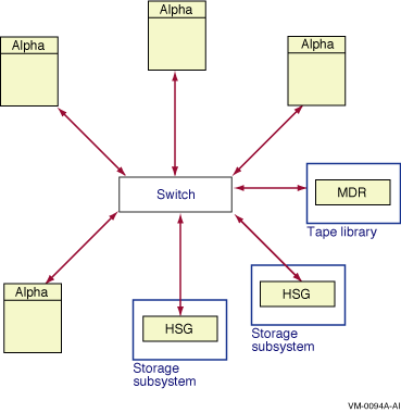
Figure 7-2 shows a physical view of a Fibre Channel switched topology. The configuration in Figure 7-2 is simplified for clarity. Typical configurations will have multiple Fibre Channel interconnects for high availability, as shown in Section 7.3.4.
Figure 7-2 Switched Topology (Physical View)
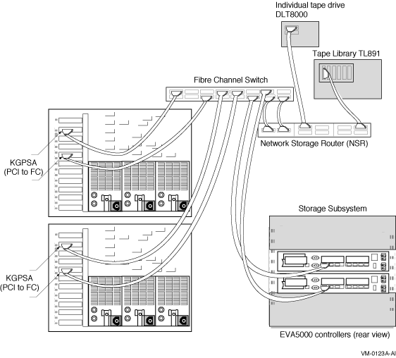
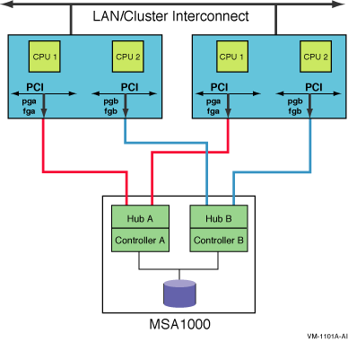
Figure 7-3 shows an arbitrated loop topology. Two hosts are connected to a dual-ported StorageWorks MSA 1000 storage system. OpenVMS supports an arbitrated loop topology only on this storage system.
Support for this topology is planned to be available soon and will be announced on the OpenVMS home page: http://www.hp.com/go/openvms . |
Figure 7-3 Arbitrated Loop Topology Using MSA 1000
OpenVMS Alpha supports the Fibre Channel devices listed in Table 7-2. For Fibre Channel fabric components supported by OpenVMS, refer to the latest version of HP StorageWorks SAN Design Reference Guide (order number AA-RMPNM-TE).
Note that Fibre Channel hardware names typically use the letter G to designate hardware that is specific to Fibre Channel. Fibre Channel configurations with other Fibre Channel equipment are not supported. To determine the required minimum versions of the operating system and firmware, see the release notes.
HP recommends that all OpenVMS Fibre Channel configurations use the latest update kit for the OpenVMS version they are running.
The root name of these kits is FIBRE_SCSI, a change from the earlier naming convention of FIBRECHAN. The kits are available from the following web site:
http://welcome.hp.com/country/us/eng/support.html |
| Component Name | Description |
|---|---|
| AlphaServer 800, 1 1000A, 2 1200, 4000, 4100, 8200, 8400, DS10, DS20, DS25, DS20E, ES40, ES45, ES47, ES80, GS60, GS60E, GS80, GS140, GS160, GS320, and GS1280 | Alpha host. |
| HP Integrity server rx1600-2, rx2600-2, rx4640-8 | HP Integrity host |
| Enterprise Virtual Array (EVA) | Fibre Channel "virtual" RAID storage with two Fibre Channel host ports and support for 240 physical Fibre Channel drives. |
| HSV110 | Fibre Channel hierarchical storage controller module (for the EVA5000) with two Fibre Channel host ports and support for 6 or 12 SCSI drive enclosures. |
| HSG80 | Fibre Channel hierarchical storage controller module with two Fibre Channel host ports and support for six SCSI drive buses. |
| HSG60 | Fibre Channel hierarchical storage controller module with two Fibre Channel host ports and support for two SCSI buses. |
| MDR | Fibre Channel Modular Data Router, a bridge to a SCSI tape or a SCSI tape library, with a 1-Gb capacity. The MDR must be connected to a Fibre Channel switch. It cannot be connected directly to an Alpha system. |
| NSR | Fibre Channel Network Storage Router, a bridge to a SCSI tape or a SCSI tape library, with a 2-Gb capacity. The NSR must be connected to a Fibre Channel switch. It cannot be connected directly to an Alpha system. |
| Fibre Channel fabric components, including host adapters, switches, bridges, Gigabit interface converters (GBICs) for long distance configurations, and cables | See the latest version of the HP StorageWorks SAN Design Reference Guide (order number: AA-RMPNM-TE). |
OpenVMS supports the Fibre Channel SAN configurations described in the latest HP StorageWorks SAN Design Reference Guide (order number: AA-RMPNM-TE) and the Data Replication Manager (DRM) user documentation. This includes support for:
The StorageWorks documentation is available from their web site, which you can access from the OpenVMS web page:
http://www.hp.com/go/openvms |
Select HP Storage (from related links in the left navigational bar). Next, locate the storage product. Then you can access the product's documentation.
Within the configurations described in the StorageWorks documentation, OpenVMS provides the following capabilities and restrictions:
This configuration support is in effect as of the revision date of this document. OpenVMS plans to increase these limits in future releases.
In addition to the configurations already described, OpenVMS also supports the SANworks Data Replication Manager. This is a remote data vaulting solution that enables the use of Fibre Channel over longer distances. For more information, see the HP StorageWorks web site, which you can access from the OpenVMS web page:
http://www.hp.com/go/openvms |
Select HP Storage (from related links in the left navigational bar). Next, locate the storage product.
Qualification of new Fibre Channel hardware and larger configurations is ongoing. New hardware and larger configurations may necessitate enhancements to the Fibre Channel support in OpenVMS. Between releases of OpenVMS, enhancements and corrections to Fibre Channel software are made available by means of remedial kits on the HP support web site at:
http://h18007.www1.hp.com.support/files/index.html |
The latest version of each kit is the one posted to the HP support web site. HP recommends that you monitor this web site.
HP also recommends that you monitor the Fibre Channel web site at:
http://h71000.www7.hp.com/openvms/fibre/ |
The Fibre Channel web site is periodically updated with important news and new slide presentations.
Shared Fibre Channel OpenVMS Cluster storage is supported in both mixed-version and mixed-architecture OpenVMS Cluster systems. Mixed-version support is described in Section 11.7. Mixed-architecture support means a combination of OpenVMS Alpha systems with either OpenVMS VAX systems or OpenVMS I64 systems. Certain restrictions apply to the size of a mixed-architecture OpenVMS Alpha and OpenVMS I64 Cluster system, as described in the HP OpenVMS Version 8.2 New Features and Documentation Overview manual.
The following configuration requirements must be observed:
Fibre Channel is supported in all OpenVMS Galaxy configurations. For more information about Galaxy configurations, see the HP OpenVMS Alpha Partitioning and Galaxy Guide.
This section presents example Fibre Channel configurations.
These configurations are valid for HSG storage controllers and for HSV storage controllers, except for Section 7.3.1 and Section 7.3.2, which apply only to HSG storage controllers. |
The configurations build on each other, starting with the smallest valid configuration and adding redundant components for increasing levels of availability, performance, and scalability.
Figure 7-4 shows a single system using Fibre Channel as a storage interconnect.
Figure 7-4 Single Host With One Dual-Ported Storage Controller
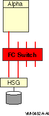
Note the following about this configuration:
Figure 7-5 shows multiple hosts connected to a dual-ported storage subsystem.
Figure 7-5 Multiple Hosts With One Dual-Ported Storage Controller
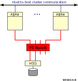
Note the following about this configuration:
Figure 7-6 Multiple Hosts With Storage Controller Redundancy
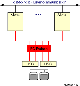
This configuration offers the following advantages:
Figure 7-7 Multiple Hosts With Multiple Independent Switches
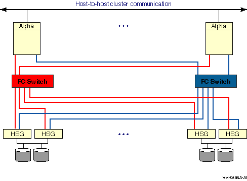
This two-switch configuration offers the advantages of the previous configurations plus the following:
Figure 7-8 Multiple Hosts With Dual Fabrics
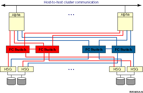
This dual-fabric configuration offers the advantages of the previous configurations plus the following advantages:
Figure 7-9 shows multiple hosts connected to two fabrics. Each fabric has four switches.
Figure 7-9 Multiple Hosts With Larger Dual Fabrics
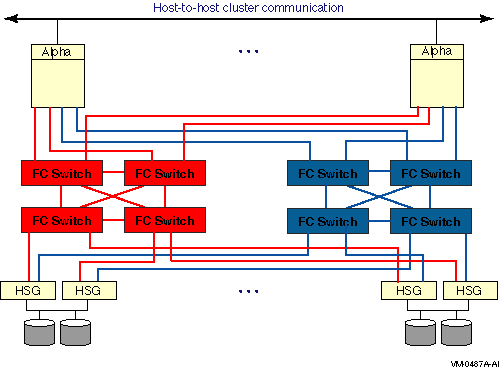
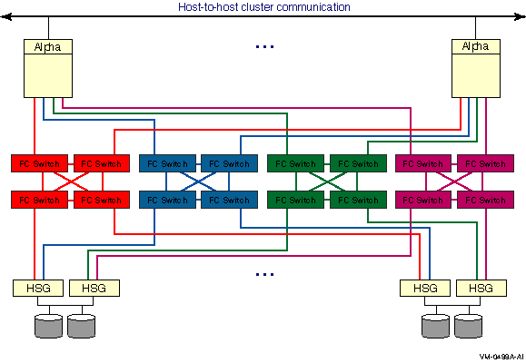
Figure 7-10 shows multiple hosts connected to four fabrics. Each fabric has four switches.
Figure 7-10 Multiple Hosts With Four Fabrics
Fibre Channel devices for disk and tape storage come with factory-assigned worldwide IDs (WWIDs). These WWIDs are used by the system for automatic FC address assignment. The FC WWIDs and addresses also provide the means for the system manager to identify and locate devices in the FC configuration. The FC WWIDs and addresses are displayed, for example, by the Alpha console and by the HSG or HSV console. It is necessary, therefore, for the system manager to understand the meaning of these identifiers and how they relate to OpenVMS device names.
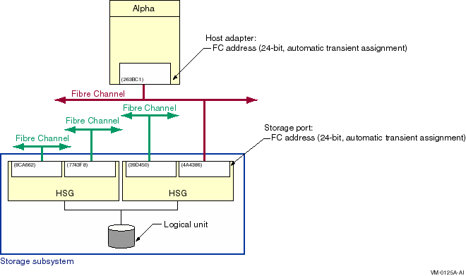
In most situations, Fibre Channel devices are configured to have temporary addresses. The device's address is assigned automatically each time the interconnect initializes. The device may receive a new address each time a Fibre Channel is reconfigured and reinitialized. This is done so that Fibre Channel devices do not require the use of address jumpers. There is one Fibre Channel address per port, as shown in Figure 7-11.
Figure 7-11 Fibre Channel Host and Port Addresses
In order to provide more permanent identification, each port on each device has a WWID, which is assigned at the factory. Every Fibre Channel WWID is unique. Fibre Channel also has node WWIDs to identify multiported devices. WWIDs are used by the system to detect and recover from automatic address changes. They are useful to system managers for identifying and locating physical devices.
Figure 7-12 shows Fibre Channel components with their factory-assigned WWIDs and their Fibre Channel addresses.
Figure 7-12 Fibre Channel Host and Port WWIDs and Addresses
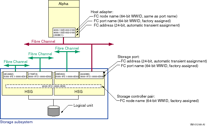
Note the following about this figure:
You can display the FC node name and FC port name for a Fibre Channel host bus adapter with the SHOW DEVICE/FULL command. For example:
$ SHOW DEVICE/FULL FGA0

Device FGA0:, device type KGPSA Fibre Channel, is online, shareable, error
    logging is enabled.

    Error count                    0    Operations completed                  0
    Owner process                 ""    Owner UIC                      [SYSTEM]
    Owner process ID        00000000    Dev Prot              S:RWPL,O:RWPL,G,W
    Reference count                0    Default buffer size                   0
    FC Port Name 1000-0000-C923-0E48    FC Node Name        2000-0000-C923-0E48
|
| Previous | Next | Contents | Index |