Software > OpenVMS Systems > Documentation > 83final > 4548 HP OpenVMS Systems Documentation |
HP OpenVMS Linker Utility Manual
To illustrate section creation, consider the sections created by the HP C compiler when it processes the sample programs in the following examples:
To see what sections the HP C compiler creates for these modules, use the ANALYZE/OBJECT utility to examine each object module. Example 3-4 presents an excerpt from the analysis of the object module MYTEST.OBJ. Only the section definitions are included in the excerpt.
The items in the following list correspond to the numbered items in Example 3-4:
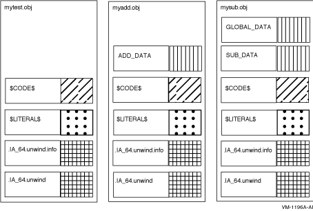
Figure 3-2 illustrates some of the sections created by the HP C compiler for the modules in Example 3-1, Example 3-2, and Example 3-3. (The shaded areas represent the settings of the section attributes the linker considers when sorting the sections into image segments in an executable image. See Section 3.3.4 for more information about how the linker creates segments in an image.) Figure 3-2 Sections Created for Examples 3-1, 3-2, and 3-3 
3.2.1 Sections Created by The LinkerUnlike the VAX and Alpha linkers, the I64 linker creates new sections as well as contributions to existing sections for loadable segments. When the linker assigns a name for a section, the name can be a reserved name containing an embedded space (e.g. $LINKER UNWIND$). The linker uses the embedded space in a reserved name to prevent you from changing the section attributes. The PSECT_ATTR option reads the embedded space and compresses it out of the name. As such, the name is not read by the linker as you intended and the attributes are preserved. 3.2.1.1 Sections for Relaxed Symbol DefinitionsIn HP C, relaxed symbol definitions that can act like a reference or a definition (when no other definition is found) have no section assigned to them. If there is no hard definition (i.e., a symbol with a compiler-supplied section), the linker allocates a section for the symbol. The section has the same name as the symbol, and is contributed by the I64 linker (labeled with <Linker> in the map). 3.2.1.2 Sections Embedded in Code SegmentsThe I64 linker contributes sections to code segments that contain calls to code outside the image, outside the code segment but to another segment within the image, or to code that can't be reached with a normal branch instruction inside the segment (called a trampoline). The instructions can be helpful when using the debugger to step into subroutines. The instructions are grouped in 128-bit bundles, with a series of dashes marking the end of a bundle. <Linker> is used to lable the linker contribution in the map, usually at the end of the code section (normally named $CODE$). The compiler is unaware whether a call is internal or external to the image being created. The linker has this knowledge and for external calls, generates the following sequence of instructions:
In the first instruction, R15 contains the address of the Function Descriptor (FD), which the linker obtained by adding an offset to the Global Pointer register (GP, implemented as R1). R16 is loaded with a pointer to the code address. R1 then receives the new Global Pointer. The branch instruction completes the call sequence.
Calls Out of the Segment to Another Segment in the Same Image
The compiler is unaware whether the destination of a call is in another segment of the same. The linker has this knowledge and for calls that cross segment boundaries, generates the following sequence of instructions:
In the first instruction, R15 contains the address of the Function Descriptor (FD), which the linker obtained by adding an offset to the Global Pointer (GP, implemented as R1) register. R16 is loaded with a pointer to the code address. Because the instructions branch to another segment in the same image and because there is one GP per image, the linker can skip copying the GP from the FD.
Calls That Cannot be Reached with Normal Branch Instruction (Trampolines)
The linker uses a trampoline when when the branch-to-code instruction in the same segment (calculated in 128 bit or 16 byte bundles) is more than 21-bit signed offset. The trampoline must be located somewhere within the original 21-bit signed branch. The trampoline then does an indirect branch from the trampoline to the target instruction.
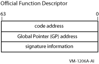
3.2.1.3 Short Data SectionsIn order to make position-independent code that does not require any relocations, Itanium platforms allow code to make a reference to pointers and other short data using offsets from an address in a register. This special register is called the Global Pointer (GP) register. The language processors place such data into sections named short data sections. It is the task of the linker to collect these sections into a segment or segments and to determine the GP value. The GP value is determined so that the beginning of the first (or only) short data segment is the negative-most offset from the GP within range. For the Intel Itanium architecture, the negative-most offset is 2 MB. Therefore, the GP value is the virtual address of the beginning of the first (or only) short data segment plus 2 MB. If the address range for your short data segment or segments is less than 2Mb, the GP value may not even point to a virtual address mapped by your image. The compilers usually place data in the short data sections that are relatively short (like quadwords or smaller) and not long (like an array). There are two kinds of short data sections --- read-only and read-write. The I64 linker is a major contributor to the read-only short data section. In this section, the linker puts addresses of data and function descriptors (termed procedure descriptors on Alpha) that can be reached by code with a short offset from the Global Pointer register. This section is named $LINKER SDATA$. In the map, <Linker> is used to label the linker contributions to this section. Function descriptors placed in the read-only short data section have varying lengths depending on their type. The types are official and local. Official function descriptors are always three quadwords long. Local function descriptors can be two quadwords or four quadwords long, depending on whether the qualifier /NONATIVE_ONLY is present. If the image is supposed to interoperate with translated images, the /NONATIVE_ONLY qualifier must be used, and local function descriptors will be four quadwords long. Official function descriptors represent functions that are defined by an image. One example of functions defined by an image are those functions which can be exported from a shareable image by the symbol vector and called by other images. Official function descriptors always contain the address of the first instruction of the function in the first quadword. The GP value under which the function executes is in the second quadword. The third quadword contains a zero, or if the /NONATIVE_ONLY qualifier is used it contains the function's signature or a pointer to the function's signature. A signature describes the parameters and return status of the function. If the third quadword is zero then the function descriptor has no signature, and a translated image is not allowed to call the function. An official function descriptor has the following format at runtime: Figure 3-3 Official Function Descriptor 
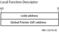
A local function descriptor represents a function outside of the image. Local function descriptors made for images that do not interoperate with translated images contain at run-time the address of the first instruction of the function in the first quadword. The GP value under which the function executes is in the second quadword. The linker generates a fixup for the function descriptor because it has no knowledge of those addresses. The fixup is applied by the image activator which has already activated the image with those addresses in it. A local function descriptor has the following format at runtime: Figure 3-4 Local Function Descriptor - Two Quadwords 
Local function descriptors made by the linker for images that can interoperate with translated images are four quadwords long. At run-time, after the image activator has determined that the target shareable image is translated, the four quadwords in the function descriptor contain the following:
The linker assumes the image activator will find a native image, and issues a fixup to the image activator to fill in the first two (of four) quadwords with the code address and GP. The third quadword is filled in with signature information, like an official function descriptor. The fourth quadword is filled in with a zero. If the image activator determines that the function referenced by this function descriptor in a native image, it applies the fixup and ignores the last two quadwords. 3.2.1.4 Section for the Symbol VectorThe symbol vector on Alpha is in a PSECT named $SYMVECT. The I64 Linker does not use a section with the name $SYMVECT, but places the symbol vector in a section with the name $LINKER SYMBOL_VECTOR$, and places the section in the short data segment by default. In the map, <Linker Option> is used to label this linker contribution. You can use the qualifier /SEGMENT=(SYMBOL_VECTOR=NOSHORT) to move $LINKER SYMBOL_VECTOR$ to a data segment which is read-only. The I64 Linker creates a read-only data segment if one does not already exist. For a look at the layout of a symbol vector see Figure 2-1. 3.2.1.5 Sections that Contain Unwind DataWhen an exception is signaled by hardware or software, the condition handling facility looks for a condition handler. If a condition handler is found, the handler may choose to call SYS$UNWIND to unwind the stack. SYS$UNWIND has, at its disposal, an unwind table. The unwind table contains a pointer into a variable-sized information block that contains the unwind descriptor list and a language-specific area. The unwind table and the unwind information block are created by the compilers. The linker has to place the contributions to the unwind tables in the same order as the contributions to the code segment for unwinding to work. The linker renames the compiler-named sections that contain unwind tables (usually named .IA_64.unwind) and unwind information blocks (usually named .IA_64_unwinfo). It can tell which sections contain unwind tables because those sections have the type SHT_IA_64_UNWIND. It also has the link order (SHF_LINK_ORDER) attribute set. The link order attribute means that the contributions to the unwind table must be in the same order as contributions pointed to by the SH_LINK field (a code section). The new, reserved name of the section that contains the unwind tables is $LINKER UNWIND$. $LINKER UNWINFO$ is the new, reserved name of the section that contains unwind information. These names appear in the linker map; the actual names of these sections are gone by the time the map is written. The linker uses reserved names for these sections; this means that you are not allowed to change the section attributes with a PSECT_ATTR= clause or collect them with the COLLECT= option to other clusters. This is because the placement and ordering of these sections are driven by the placement and ordering of the code sections to which they refer. By altering the placement or ordering of the code sections through the use of linker options or input file ordering, the sections containing unwind tables and unwind information blocks will likewise have the placement or ordering of their contributions altered. $LINKER UNWIND$ and $LINKER UNWINFO$ have identical significant attributes and therefore end up in the same unwind segment. This is denoted in the Image Segment Synopsis section of the map by the [UNWIND] tag. The unwind segment is connected to the corresponding code segment by entries in the dynamic segment (which the image activator uses for activating an image). If you have a complex link with an options file that contains a number of CLUSTER= or COLLECT= options, you may have more unwind segments than you really need. The I64 linker constructs one unwind segment per cluster with one or more code segments. To reduce the number of unwind segments, you should reduce the number of clusters containing code. This is done by collecting code sections onto a smaller number of clusters or onto a single cluster. 3.3 Creating SegmentsOn I64 systems, the linker creates segments, which are analogous to image sections on Alpha and VAX systems. Segments define the memory requirements and page protection characteristics of an image. To create segments, the linker processes the sections in the object modules specified in the link operation. The number and type of segments the linker creates depend on the input files and what is specified in the link operation. Section 3.3.1 describes how the clustering of input files affects segment creation. Section 3.3.2 describes the effects of section attributes on segment creation.
|