Software > OpenVMS Systems > Documentation > 84final > 4477 HP OpenVMS Systems Documentation |
HP OpenVMS Cluster Systems
F.6.2 Techniques for TroubleshootingWhen there is a break in communications between two nodes and you suspect problems with channel formation, follow these instructions:
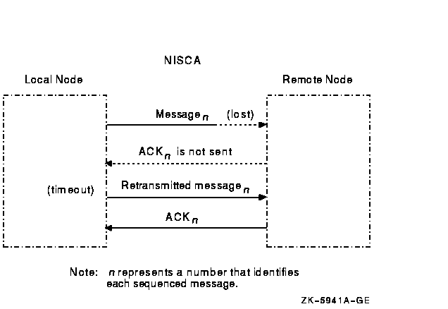
F.7 Retransmission ProblemsRetransmissions occur when the local node does not receive acknowledgment of a message in a timely manner. F.7.1 Why Retransmissions OccurThe first time the sending node transmits the datagram containing the sequenced message data, PEDRIVER sets the value of the REXMT flag bit in the TR header to 0. If the datagram requires retransmission, PEDRIVER sets the REXMT flag bit to 1 and resends the datagram. PEDRIVER retransmits the datagram until either the datagram is received or the virtual circuit is closed. If multiple channels are available, PEDRIVER attempts to retransmit the message on a different channel in an attempt to avoid the problem that caused the retransmission. Retransmission typically occurs when a node runs out of a critical resource, such as large request packets (LRPs) or nonpaged pool, and a message is lost after it reaches the remote node. Other potential causes of retransmissions include overloaded LAN bridges, slow LAN adapters (such as the DELQA), and heavily loaded systems, which delay packet transmission or reception. Figure F-4 shows an unsuccessful transmission followed by a successful retransmission. Figure F-4 Lost Messages Cause Retransmissions 
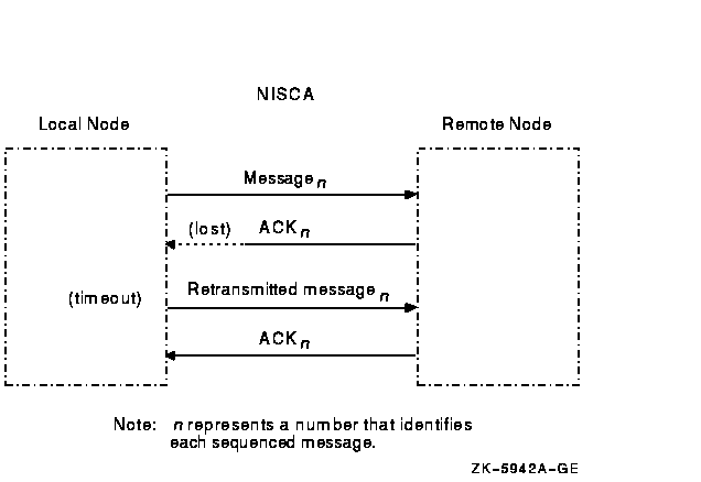
Because the first message was lost, the local node does not receive acknowledgment (ACK) from the remote node. The remote node acknowledged the second (successful) transmission of the message. Retransmission can also occur if the cables are seated improperly, if the network is too busy and the datagram cannot be sent, or if the datagram is corrupted or lost during transmission either by the originating LAN adapter or by any bridges or repeaters. Figure F-5 illustrates another type of retransmission. Figure F-5 Lost ACKs Cause Retransmissions 
In Figure F-5, the remote node receives the message and transmits an acknowledgment (ACK) to the sending node. However, because the ACK from the receiving node is lost, the sending node retransmits the message. F.7.2 Techniques for TroubleshootingYou can troubleshoot cluster retransmissions using a LAN protocol analyzer for each LAN segment. If multiple segments are used for cluster communications, then the LAN analyzers need to support a distributed enable and trigger mechanism (see Section F.9).Reference: Techniques for isolating the retransmitted datagram using a LAN analyzer are discussed in Section F.11.2. See also Appendix G for more information about congestion control and PEDRIVER message retransmission. F.8 Understanding NISCA DatagramsTroubleshooting NISCA protocol communication problems requires an understanding of the NISCA protocol packet that is exchanged across the OpenVMS Cluster system. F.8.1 Packet FormatThe format of packets on the NISCA protocol is defined by the $NISCADEF macro, which is located in [DRIVER.LIS] on VAX systems and in [LIB.LIS] for Alpha systems on your CD listing disk. Figure F-6 shows the general form of NISCA datagrams. A NISCA datagram consists of the following headers, which are usually followed by user data:
Figure F-6 NISCA Headers 
Caution: The NISCA protocol is subject to change without notice. F.8.2 LAN HeadersThe NISCA protocol is supported on LANs consisting of Ethernet, described in Section F.8.3 . These headers contain information that is useful for diagnosing problems that occur between LAN adapters. Reference: See Section F.10.4 for methods of isolating information in LAN headers. F.8.3 Ethernet HeaderEach datagram that is transmitted or received on the Ethernet is prefixed with an Ethernet header. The Ethernet header, shown in Figure F-7 and described in Table F-8, is 16 bytes long. Figure F-7 Ethernet Header 
F.8.4 Datagram Exchange (DX) HeaderThe datagram exchange (DX) header for the OpenVMS Cluster protocol is used to address the data to the correct OpenVMS Cluster node. The DX header, shown in Figure F-8 and described in Table F-9, is 14 bytes long. It contains information that describes the OpenVMS Cluster connection between two nodes. See Section F.10.3 about methods of isolating data for the DX header. Figure F-8 DX Header 
F.8.5 Channel Control (CC) HeaderThe channel control (CC) message is used to form and maintain working network paths between nodes in the OpenVMS Cluster system. The important fields for network troubleshooting are the datagram flags/type and the cluster password. Note that because the CC and TR headers occupy the same space, there is a TR/CC flag that identifies the type of message being transmitted over the channel. Figure F-9 shows the portions of the CC header needed for network troubleshooting, and Table F-10 describes these fields. Figure F-9 CC Header 
F.8.6 Transport (TR) HeaderThe transport (TR) header is used to pass SCS datagrams and sequenced messages between cluster nodes. The important fields for network troubleshooting are the TR datagram flags, message acknowledgment, and sequence numbers. Note that because the CC and TR headers occupy the same space, a TR/CC flag identifies the type of message being transmitted over the channel. Figure F-10 shows the portions of the TR header that are needed for network troubleshooting, and Table F-11 describes these fields. Figure F-10 TR Header 
Note: The TR header shown in Figure F-10 is used when both nodes are running Version 1.4 or later of the NISCA protocol. If one or both nodes are running Version 1.3 or an earlier version of the protocol, then both nodes will use the message acknowledgment and sequence number fields in place of the extended message acknowledgment and extended sequence number fields, respectively.
F.9 Using a LAN Protocol Analysis ProgramSome failures, such as packet loss resulting from congestion, intermittent network interruptions of less than 20 seconds, problems with backup bridges, and intermittent performance problems, can be difficult to diagnose. Intermittent failures may require the use of a LAN analysis tool to isolate and troubleshoot the NISCA protocol levels described in Section F.1. As you evaluate the various network analysis tools currently available, you should look for certain capabilities when comparing LAN analyzers. The following sections describe the required capabilities. F.9.1 Single or Multiple LAN SegmentsWhether you need to troubleshoot problems on a single LAN segment or on multiple LAN segments, a LAN analyzer should help you isolate specific patterns of data. Choose a LAN analyzer that can isolate data matching unique patterns that you define. You should be able to define data patterns located in the data regions following the LAN header (described in Section F.8.2). In order to troubleshoot the NISCA protocol properly, a LAN analyzer should be able to match multiple data patterns simultaneously. To troubleshoot single or multiple LAN segments, you must minimally define and isolate transmitted and retransmitted data in the TR header (see Section F.8.6). Additionally, for effective network troubleshooting across multiple LAN segments, a LAN analysis tool should include the following functions:
The purpose of distributed enable and distributed combination trigger functions is to capture packets as they travel across multiple LAN segments. The implementation of these functions discussed in the following sections use multicast messages to reach all LAN segments of the extended LAN in the system configuration. By providing the ability to synchronize several LAN analyzers at different locations across multiple LAN segments, the distributed enable and combination trigger functions allow you to troubleshoot LAN configurations that span multiple sites over several miles. F.9.2 Multiple LAN SegmentsTo troubleshoot multiple LAN segments, LAN analyzers must be able to capture the multicast packets and dynamically enable the trigger function of the LAN analyzer, as follows:
The HP 4972A LAN Protocol Analyzer, available from the Hewlett-Packard Company, is one example of a network failure analysis tool that provides the required functions described in this section. Reference: Section F.11 provides examples that use the HP 4972A LAN Protocol Analyzer.
|