Software > OpenVMS Systems > Documentation > 84final > 6318 HP OpenVMS Systems Documentation |
Guidelines for OpenVMS Cluster Configurations
6.7.10 Automatic Failback to a Direct Path (Disks Only)Multipath failover, as described in Section 6.7.9, applies to MSCP served paths as well. That is, if the current path is via an MSCP served path and the served path fails, mount verification can trigger an automatic failover back to a working direct path. However, an I/O error on the MSCP path is required to trigger the failback to a direct path. Consider the following sequence of events:
In this case, the system would continue to use the MSCP served path to the device, even though the direct path is preferable. This is because no error occurred on the MSCP served path to provoke the path selection procedure. The automatic failback feature is designed to address this situation. Multipath polling attempts to fail back the device to a direct path when it detects that all of the following conditions apply:
The automatic failback is attempted by triggering mount verification and, as a result, the automatic failover procedure on the device. The main purpose of multipath polling is to test the status of unused paths in order to avoid situations such as the following:
The poller would detect the failure of path B within 1 minute of its failure and would issue an OPCOM message. An alert system manager can initiate corrective action immediately. Note that a device might successfully respond to the SCSI INQUIRY commands that are issued by the path poller but might fail to complete a path switch or mount verification successfully on that path. A system manager or operator can control automatic failback in three ways:
Because of the path selection procedure, the automatic failover procedure, and the automatic failback feature, the current path to a mounted device is usually a direct path when there are both direct and MSCP served paths to that device. The primary exceptions to this are when the path has been manually switched to the MSCP served path or when there are no working direct paths. 6.7.11 Enabling or Disabling Paths as Path Switch CandidatesBy default, all paths are candidates for path switching. You can disable or re-enable a path as a switch candidate by using the SET DEVICE command with the /[NO]ENABLE qualifier. The reasons you might want to do this include the following:
Note that the current path cannot be disabled. The command syntax for enabling a disabled path is:
The following command enables the MSCP served path of device $2$DKA502.
The following command disables a local path of device $2$DKA502.
Be careful when disabling paths. Avoid creating an invalid configuration, such as the one shown in Figure 6-21. 6.7.12 Performance ConsiderationsThe presence of an MSCP served path in a disk multipath set has no measurable effect on steady-state I/O performance when the MSCP path is not the current path. Note that the presence of an MSCP served path in a multipath set might increase the time it takes to find a working path during mount verification under certain, unusual failure cases. Because direct paths are tried first, the presence of an MSCP path should not affect recovery time. However, the ability to switch dynamically from a direct path to an MSCP served path might significantly increase the I/O serving load on a given MSCP server system with a direct path to the multipath disk storage. Because served I/O takes precedence over almost all other activity on the MSCP server, failover to an MSCP served path can affect the reponsiveness of other applications on that MSCP server, depending on the capacity of the server and the increased rate of served I/O requests. For example, a given OpenVMS Cluster configuration might have sufficient CPU and I/O bandwidth to handle an application work load when all the shared SCSI storage is accessed by direct SCSI paths. Such a configuration might be able to work acceptably as failures force a limited number of devices to switch over to MSCP served paths. However, as more failures occur, the load on the MSCP served paths could approach the capacity of the cluster and cause the performance of the application to degrade to an unacceptable level. The MSCP_BUFFER and MSCP_CREDITS system parameters allow the system manager to control the resources allocated to MSCP serving. If the MSCP server does not have enough resources to serve all incoming I/O requests, performance will degrade on systems that are accessing devices on the MSCP path on this MSCP server. You can use the MONITOR MSCP command to determine whether the MSCP server is short of resources. If the Buffer Wait Rate is nonzero, the MSCP server has had to stall some I/O while waiting for resources. It is not possible to recommend correct values for these parameters. However, note that, starting with OpenVMS Alpha Version 7.2-1, the default value for MSCP_BUFFER has been increased from 128 to 1024. As noted in the online help for the SYSGEN utility, MSCP_BUFFER specifies the number of pagelets to be allocated to the MSCP server's local buffer area, and MSCP_CREDITS specifies the number of outstanding I/O requests that can be active from one client system. For example, a system with many disks being served to several OpenVMS systems might have MSCP_BUFFER set to a value of 4000 or higher and MSCP_CREDITS set to 128 or higher. For information about modifying system parameters, see the OpenVMS System Manager's Manual. HP recommends that you test configurations that rely on failover to MSCP served paths at the worst-case load level for MSCP served paths. If you are configuring a multiple-site disaster-tolerant cluster that uses a multiple-site SAN, consider the possible failures that can partition the SAN and force the use of MSCP served paths. In a symmetric dual-site configuration, HP recommends that you provide capacity for 50 percent of the SAN storage to be accessed by an MSCP served path. You can test the capacity of your configuration by using manual path switching to force the use of MSCP served paths. 6.7.13 Console ConsiderationsThis section describes how to use the console with parallel SCSI multipath disk devices. See Section 7.6 for information on using the console with FC multipath devices. The console uses traditional, path-dependent, SCSI device names. For example, the device name format for disks is DK, followed by a letter indicating the host adapter, followed by the SCSI target ID, and the LUN. This means that a multipath device will have multiple names, one for each host adapter it is accessible through. In the following sample output of a console show device command, the console device name is in the left column. The middle column and the right column provide additional information, specific to the device type. Notice, for example, that the devices dkb100 and dkc100 are really two paths to the same device. The name dkb100 is for the path through adapter PKB0, and the name dkc100 is for the path through adapter PKC0. This can be determined by referring to the middle column, where the informational name includes the HSZ allocation class. The HSZ allocation class allows you to determine which console "devices" are really paths to the same HSZ device.
The console does not automatically attempt to use an alternate path to a device if I/O fails on the current path. For many console commands, however, it is possible to specify a list of devices that the console will attempt to access in order. In a multipath configuration, you can specify a list of console device names that correspond to the multiple paths of a device. For example, a boot command, such as the following, will cause the console to attempt to boot the multipath device through the DKB100 path first, and if that fails, it will attempt to boot through the DKC100 path:
Chapter 7
|
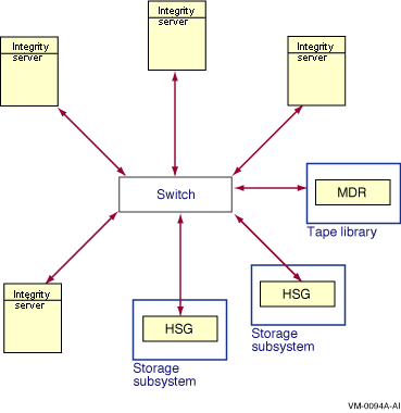
The Fibre Channel interconnect is shown generically in the figures in this chapter. It is represented as a horizontal line to which the node and storage subsystems are connected. Physically, the Fibre Channel interconnect is always radially wired from a switch, as shown in Figure 7-1. The representation of multiple SCSI disks and SCSI buses in a storage subsystem is also simplified. The multiple disks and SCSI buses, which one or more HSGx controllers serve as a logical unit to a host, are shown in the figures as a single logical unit. For ease of reference, the term HSG, which represents a Fibre Channel hierarchical storage controller, is used throughout this chapter to represent both an HSG60 and an HSG80, except where it is important to note any difference, as in the Software Product Description for Fibre Channel Hardware Components. |
Fibre Channel is an ANSI standard network and storage interconnect that offers many advantages over other interconnects. Its most important features and the support offered by OpenVMS for these features are shown in Table 7-1.
| Feature | OpenVMS Support |
|---|---|
| High-speed transmission | OpenVMS supports 2 Gb/s, full-duplex, serial interconnect (can simultaneously transmit and receive 200 MB of data per second). |
| Choice of media | OpenVMS supports fiber-optic media. |
| Long interconnect distances | OpenVMS supports multimode fiber-optic media at 500 meters per link and single-mode fiber-optic media (for interswitch links [ISLs]) for distances up to 100 kilometers per link. |
| Multiple protocols | OpenVMS supports SCSI--3. Possible future support for IP. |
| Numerous topologies | OpenVMS supports switched FC (highly scalable, multiple concurrent communications) and multiple switches (fabric). Support is planned for arbitrated loop on the StorageWorks Modular Storage Array (MSA) 1000 storage system, only, and will be announced on the OpenVMS home page: http://www.hp.com/go/openvms. |
Figure 7-1 shows a logical view of a switched topology. The FC nodes are either Alpha hosts, or storage subsystems. Each link from a node to the switch is a dedicated FC connection. The switch provides store-and-forward packet delivery between pairs of nodes. Concurrent communication between disjoint pairs of nodes is supported by the switch.
Figure 7-1 Switched Topology (Logical View)

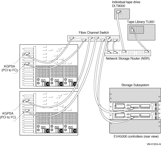
Figure 7-2 shows a physical view of a Fibre Channel switched topology. The configuration in Figure 7-2 is simplified for clarity. Typical configurations will have multiple Fibre Channel interconnects for high availability, as shown in Section 7.3.4.
Figure 7-2 Switched Topology (Physical View)

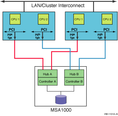
Figure 7-3 shows an arbitrated loop topology. Two hosts are connected to a dual-ported StorageWorks MSA 1000 storage system. OpenVMS supports an arbitrated loop topology only on this storage system.
Support for this topology is planned to be available soon and will be announced on the OpenVMS home page: http://www.hp.com/go/openvms |
Figure 7-3 Arbitrated Loop Topology Using MSA 1000

OpenVMS supports the Fibre Channel devices listed in the Software Product Description. For Fibre Channel fabric components supported by OpenVMS, refer to the latest version of HP StorageWorks SAN Design Reference Guide (order number AA-RMPNM-TE).
Note that Fibre Channel hardware names typically use the letter G to designate hardware that is specific to Fibre Channel. Fibre Channel configurations with other Fibre Channel equipment are not supported. To determine the required minimum versions of the operating system and firmware, see the release notes.
HP recommends that all OpenVMS Fibre Channel configurations use the latest update kit for the OpenVMS version they are running.
The root name of these kits is FIBRE_SCSI, a change from the earlier naming convention of FIBRECHAN. The kits are available from the following web site:
http://welcome.hp.com/country/us/eng/support.html
OpenVMS supports the Fibre Channel SAN configurations described in the latest HP StorageWorks SAN Design Reference Guide and the Data Replication Manager (DRM) user documentation. This includes support for:
The StorageWorks documentation is available from their web site, which you can access from the OpenVMS web page:
Select HP Storage (from related links in the left navigational bar). Next, locate the storage product. Then you can access the product's documentation.
Within the configurations described in the StorageWorks documentation, OpenVMS provides the following capabilities and restrictions:
This configuration support is in effect as of the revision date of this document. OpenVMS plans to increase these limits in future releases.
In addition to the configurations already described, OpenVMS also supports the SANworks Data Replication Manager. This is a remote data vaulting solution that enables the use of Fibre Channel over longer distances. For more information, see the HP StorageWorks web site, which you can access from the OpenVMS web page:
Select HP Storage (from related links in the left navigational bar). Next, locate the storage product.
| Previous | Next | Contents | Index |