Software > OpenVMS Systems > Documentation > 84final > 6318 HP OpenVMS Systems Documentation |
Guidelines for OpenVMS Cluster Configurations
B.1.4 Backup Interconnect for High-Availability ConfigurationsMEMORY CHANNEL requires a central hub in configurations of three or more nodes. The MEMORY CHANNEL hub contains active, powered electronic components. In the event of a hub failure, resulting from either a power shutdown or component failure, the MEMORY CHANNEL interconnect ceases operation. This type of failure does not occur with the other cluster interconnects, such as CI, DSSI, and most LAN configurations. HP therefore recommends that customers with MEMORY CHANNEL configurations who have high availability requirements consider using one of the following configurations to provide a second backup interconnect:
B.1.5 Software RequirementsThe use of MEMORY CHANNEL imposes certain requirements on memory and on your choice of diagnostic tools. B.1.5.1 Memory RequirementsMEMORY CHANNEL consumes memory during normal operations. Each system in your MEMORY CHANNEL cluster must have at least 128 MB of memory. B.1.5.2 Large-Memory Systems' Use of NPAGEVIR ParameterOn systems containing very large amounts of nonpaged pool memory, MEMORY CHANNEL may be unable to complete initialization. If this happens, the console displays the following message repeatedly:
To fix this problem, examine the value of the SYSGEN parameter NPAGEVIR. If its value is greater than 1 gigabyte, consider lowering it to about half of that. Thereafter, a reboot of your system should allow the MEMORY CHANNEL to complete initialization. B.1.6 ConfigurationsFigure B-4 shows a basic MEMORY CHANNEL cluster that uses the SCSI interconnect for storage. This configuration provides two advantages: high performance on the MEMORY CHANNEL interconnect and low cost on the SCSI interconnect. Figure B-4 MEMORY CHANNEL- and SCSI-Based Cluster 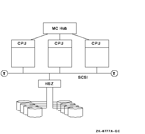
In a configuration like the one shown in Figure B-4, the MEMORY CHANNEL interconnect handles internode communication while the SCSI bus handles storage communication. You can integrate MEMORY CHANNEL with your current systems. Figure B-5 shows an example of how to add MEMORY CHANNEL to a mixed-architecture CI- and SCSI-based cluster. In this example, the BI- and XMI-based VAX systems are joined in the same CI cluster with the PCI-based Alpha MEMORY CHANNEL systems. Figure B-5 MEMORY CHANNEL CI- and SCSI-Based Cluster 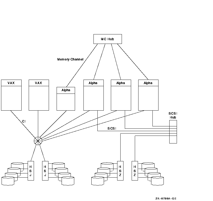
Because the MEMORY CHANNEL interconnect is not used for storage and booting, you must provide access to a boot device through one of the other interconnects. To use Figure B-5 as an example, one of the CI-based disks would be a good choice for a boot device because all nodes have direct access to it over the CI. MEMORY CHANNEL can also be integrated into an existing DSSI cluster, as shown in Figure B-6. Figure B-6 MEMORY CHANNEL DSSI-Based Cluster 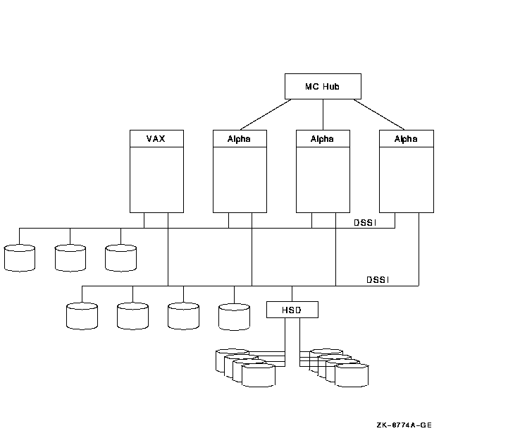
As Figure B-6 shows, the three MEMORY CHANNEL systems and the VAX system have access to the storage that is directly connected to the DSSI interconnect as well as to the SCSI storage attached to the HSD controller. In this configuration, MEMORY CHANNEL handles the Alpha internode traffic, while the DSSI handles the storage traffic. B.1.6.1 Configuration SupportMEMORY CHANNEL supports the platforms and configurations shown in Table B-1.
B.2 Technical OverviewThis section describes in more technical detail how MEMORY CHANNEL works. B.2.1 Comparison With Traditional Networks and SMPYou can think of MEMORY CHANNEL as a form of "stretched SMP bus" that supports enough physical distance to interconnect up to eight systems. However, MEMORY CHANNEL differs from an SMP environment where multiple CPUs can directly access the same physical memory. MEMORY CHANNEL requires each node to maintain its own physical memory, even though the nodes share MEMORY CHANNEL global address space. MEMORY CHANNEL fills a price/performance gap between the high performance of SMP systems and traditional packet-based networks. Table B-2 shows a comparison among the characteristics of SMP, MEMORY CHANNEL, and standard networks.
B.2.2 MEMORY CHANNEL in the OpenVMS Cluster ArchitectureAs Figure B-7 shows, MEMORY CHANNEL functionality has been implemented in the OpenVMS Cluster architecture just below the System Communication Services layer. This design ensures that no changes are required to existing applications because higher layers of OpenVMS Cluster software are unchanged.Figure B-7 OpenVMS Cluster Architecture and MEMORY CHANNEL 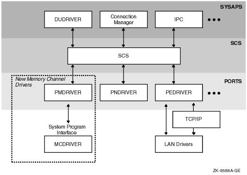
MEMORY CHANNEL software consists of two new drivers:
B.2.3 MEMORY CHANNEL AddressingIn a MEMORY CHANNEL configuration, a section of system physical address space is shared among all nodes. When a system writes data to this address space, the MEMORY CHANNEL hardware also performs a global write so that this data is stored in the memories of other systems. In other words, when a node's CPU writes data to the PCI address space occupied by the MEMORY CHANNEL adapter, the data is sent across the MEMORY CHANNEL interconnect to the other nodes. The other nodes' PCI adapters map this data into their own memory. This infrastructure enables a write to an I/O address on one system to get mapped to a physical address on the other system. The next two figures explain this in more detail. Figure B-8 shows how MEMORY CHANNEL global address space is addressed in physical memory. Figure B-8 Physical Memory and I/O Address Space 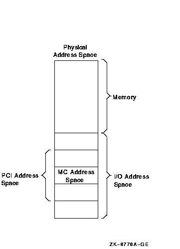
Figure B-8 shows the typical address space of a system, divided into physical memory and I/O address space. Within the PCI I/O address space, MEMORY CHANNEL consumes 128 to 512 MB of address space. Therefore, the MEMORY CHANNEL PCI adapter can be addressed within this space, and the CPU can write data to it. Every system in a MEMORY CHANNEL cluster allocates this address space for MEMORY CHANNEL data and communication. By using this address space, a CPU can perform global writes to the memories of other nodes. To explain global writes more fully, Figure B-9 shows the internal bus architecture of two nodes, node A and node B. Figure B-9 MEMORY CHANNEL Bus Architecture 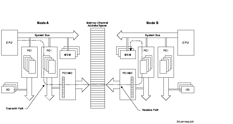
In the example shown in Figure B-9, node A is performing a global write to node B's memory, in the following sequence:
If all nodes in the cluster agree to address MEMORY CHANNEL global address space in the same way, they can virtually "share" the same address space and the same data. This is why MEMORY CHANNEL address space is depicted as a common, central address space in Figure B-9. MEMORY CHANNEL global address space is divided into pages of 8 KB (8,192 bytes). These are called MC pages. These 8 KB pages can be mapped similarly among systems. The "shared" aspect of MEMORY CHANNEL global address space is set up using the page control table, or PCT, in the PCI adapter. The PCT has attributes that can be set for each MC page. Table B-3 explains these attributes.
B.2.4 MEMORY CHANNEL ImplementationMEMORY CHANNEL software comes bundled with the OpenVMS Cluster software. After setting up the hardware, you configure the MEMORY CHANNEL software by responding to prompts in the CLUSTER_CONFIG.COM procedure. A prompt asks whether you want to enable MEMORY CHANNEL for node-to-node communications for the local computer. By responding "Yes", MC_SERVICES_P2, the system parameter that controls whether MEMORY CHANNEL is in effect, is set to 1. This setting causes the driver, PMDRIVER, to be loaded and the default values for the other MEMORY CHANNEL system parameters to take effect. For a description of all the MEMORY CHANNEL system parameters, refer to the HP OpenVMS Cluster Systems manual. For more detailed information about setting up the MEMORY CHANNEL hub, link cables, and PCI adapters, see the MEMORY CHANNEL User's Guide, order number EK-PCIMC-UG.A01.
Appendix C
|
To gain the benefits of disaster tolerance across a multiple-site OpenVMS Cluster, use Disaster Tolerant Cluster Services for OpenVMS, a system management and software package from HP. Consult your HP Services representative for more information. |
Some of the benefits you can realize with a multiple-site OpenVMS Cluster system include the following:
| Benefit | Description |
|---|---|
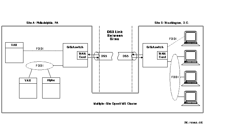
| Remote satellites and nodes | A few systems can be remotely located at a secondary site and can benefit from centralized system management and other resources at the primary site, as shown in Figure C-2. For example, a main office data center could be linked to a warehouse or a small manufacturing site that could have a few local nodes with directly attached site-specific devices. Alternatively, some engineering workstations could be installed in an office park across the city from the primary business site. |
| Data center management consolidation | A single management team can manage nodes located in data centers at multiple sites. |
| Physical resource sharing | Multiple sites can readily share devices such as high-capacity computers, tape libraries, disk archives, or phototypesetters. |
| Remote archiving | Backups can be made to archival media at any site in the cluster. A common example would be to use disk or tape at a single site to back up the data for all sites in the multiple-site OpenVMS Cluster. Backups of data from remote sites can be made transparently (that is, without any intervention required at the remote site). |
| Increased availability |
In general, a multiple-site OpenVMS Cluster provides all of the
availability advantages of a LAN OpenVMS Cluster. Additionally, by
connecting multiple, geographically separate sites, multiple-site
OpenVMS Cluster configurations can increase the availability of a
system or elements of a system in a variety of ways:
|
Figure C-2 shows an OpenVMS Cluster system with satellites accessible from a remote site.
Figure C-2 Multiple-Site OpenVMS Cluster Configuration with Remote Satellites
| Previous | Next | Contents | Index |