The basic terminal I/O
functions are read, write, set mode, set characteristics, sense mode,
and sense characteristics. All I/O functions can take function modifiers.
5.3.1 Read
When a read function
code is issued, the user-specified buffer is filled with characters
from the associated terminal. The operating system provides the following
read function codes:
IO$_READVBLK—Read
virtual block
IO$_READLBLK—Read
logical block
IO$_READPROMPT—Read
with prompt
Read operations are terminated if either of the
following two conditions occurs:
The following device- or function-dependent arguments
are used with the read function codes. The codes can take all six
arguments (P1 through P6) on QIO requests. The descriptions for these
arguments differ when itemlist read operations are performed (see “Itemlist Read Operations”).
P1—The starting
virtual address of the buffer that is to receive the data read.
P2—The size of
the buffer that is to receive the data read in bytes. (The system
generation parameter, MAXBUF, and the terminal driver limit the maximum
size of the buffer. The terminal driver only functions with buffer
sizes less than 32718 bytes.)
P3—Read with timeout,
timeout count (see Table 5-6,
IO$M_TIMED).
P5—The starting
virtual address of the prompt buffer that is to be written to the
terminal; for read with prompt operations using the IO$_READPROMPT
function code. (This argument is specified as a value rather than
an address as in the P1 argument.)
P6—The size of
the prompt buffer that is to be written to the terminal; for read
with prompt operations using the IO$_READPROMPT function code.
In a read with prompt operation, the P5 and P6
arguments specify the address and size of a prompt string buffer containing
data to be written to the terminal before the input data is read.
In a read with prompt operation, both read and write operations are
performed on the specified terminal. The prompt string buffer is formatted
like any other write buffer. If cursor position specifiers are supplied,
they are not interpreted by the driver but passed to the terminal.
During a
read with prompt operation, pressing Ctrl/O (which is turned off at
the start of any read operation) stops the prompt string. If you press
either Ctrl/U or Ctrl/X, the entire prompt string is written out again,
and the current input is ignored. If you press Ctrl/R, the current
prompt string and input are written to the terminal.
Depending on the terminal type and your input,
the prompt string can be very simple or quite complex—from
single command prompts to screen fills followed by input data. HP
recommends that prompt strings contain only one leading line feed.
In PASTHRU mode, data received from the associated
terminal is placed in the user buffer as binary information without
interpretation. (Prompts are not refreshed after a broadcast in PASTHRU
mode.)
5.3.1.1 Function Modifier Codes for Read QIO Functions
Eight function modifiers can be specified with
IO$_READVBLK, IO$_READLBLK, and IO$_READPROMPT. Table 5-6 lists these function modifiers and IO$_EXTEND,
which is described in Section “Itemlist Read Operations”. All read function modifiers are
supported for LAT devices.
Table 5-6 Read QIO Function Modifiers for the Terminal Driver
Code
Consequence
IO$M_CVTLOW
Lowercase alphabetic
characters (hexadecimal 61 to 7A) are converted to uppercase when
transferred to the user buffer or echoed. This characteristic is used
only for IO$_READLBLK, IO$_READVBLK, and IO$_READPROMPT.
IO$M_DSABLMBX
The mailbox is disabled
for unsolicited data.
IO$M_ESCAPE
A valid ANSI escape sequence
is recognized as a valid delimiter for
the read operation. The TT$M_ESCAPE characteristic is overridden by
this modifier for the current read operation.
IO$M_EXTEND
This characteristic provides
additional functionality for read operations (see “Itemlist Read Operations”). Do not specify IO$M_EXTEND with
other function modifiers.
IO$M_NOECHO
Characters are not echoed as they are entered at the keyboard.
The terminal line can also be set to a “no echo” mode
by the set mode characteristic TT$M_NOECHO, which inhibits all read
operation echoing. Setting IO$M_NOECHO also disables line editing.
IO$M_NOFILTR
The terminal does not
interpret Ctrl/U, Ctrl/R, or DEL. They are passed to the user. IO$M_NOFILTR
explicitly disables line editing.
IO$M_PURGE
The type-ahead buffer
is purged before the read operation begins.
IO$M_TIMED
The P3 argument specifies
the maximum time (seconds) that can elapse between characters received
from the terminal (the timeout value for the operation), only if IO$M_TIMED
is specified as a modifier on the read function code.
Note that if you are using a timeout in an item list of a $QIO read
to a terminal driver, the timeout on an extend read must go into the
item list.
Because
driver timing operates on a 1-second timer, a 2-second timeout must
be specified to guarantee a 1-second wait. The timer starts when the
prompt echo is started. If the read time exceeds the time specified
in P3, a timeout error (SS$_TIMEOUT) is returned in the read IOSB.
All input characters received before the read operation timed
out are returned in the user's buffer.
A read with
timeout operation, in which the timeout value is 0, empties the type-ahead
buffer into the user buffer until the proper termination condition
is reached (buffer full, termination character detected, or type-ahead
buffer empty). The read operation then returns the count of characters
read and, if a terminator is read, SS$_NORMAL; SS$_TIMEOUT is returned
if no terminator is read. In either case the offset to terminator
in the IOSB always indicates the number of characters read.
If a write request is active and there is no prompt string,
the read request generally times out with zero bytes of data being
returned.
If a read operation is interrupted by either
a broadcast write or a synchronous write request, the timer operation
is restarted.
IO$M_TRMNOECHO
The termination character (if any)
is not echoed. There is no formal
terminator if the buffer is filled before the terminator is typed.
5.3.1.2 Read Function Terminators
The P4 argument to a read QIO function either
specifies the terminator set for the read function or points to the
location containing the terminator set. If P4 is 0, all ASCII characters
with a code in the range 0 through 31 (hexadecimal 0 through 1F),
except LF, VT, FF, TAB, and BS, are terminators (see Appendix C). This is the RMS standard
terminator set. The delete character (hexadecimal 7F) and 8-bit controls
in the range 128 through 159, and 255 (hexadecimal 80 through 9F,
and FF) are also terminators. If line editing is enabled, only Return,
Ctrl/Z, or an escape sequence terminates a read operation.
If P4 does not equal 0, it contains the address
of a quadword that either specifies a terminator character bit mask or points to a location containing
that mask. (Note that if P4 references an address in a MACRO program,
a number sign (#) must precede the address; for example, P4=#TMASK.)
The quadword has a short form and a long form, as shown in Figure 5-3. In the short form, the
correspondence is between the bit number and the binary value of the
character; the character is a terminator if the bit is set. For example,
if bit 0 is set, NULL is a terminator; if bit 9 is set, TAB is a terminator.
If a character is not specified, it is not a terminator. Since ASCII
control characters are in the range 0 through 31, the short form can
be used in most cases.
The long form allows use of a more comprehensive
set of terminator characters. Any mask equal to or greater than 1
byte is acceptable. For example, a mask size of 16 bytes allows all
7-bit ASCII characters to be used as terminators; a mask size of 32
bytes allows all 8-bit characters to be used as terminators for 8-bit
terminals.
If the terminator mask is all zeros, there are
no specified terminators. The read operation ends when the specified
number of bytes (characters) have been transferred to the input buffer.
Certain control keys will not act as terminators
unless IO$M_NOFILTR is specified or the line has the TT2$M_PASTHRU
characteristic (see “Control Characters and Special Keys”).
Figure 5-3 Short and Long Forms of Terminator Mask Quadwords
5.3.1.3 Itemlist Read Operations
Itemlist read operations
provide expanded software features to read QIO requests. The operating
system provides the following combination of function code and modifier:
No other function modifiers
can be specified in an itemlist read request.
NOTE: Itemlist read features supported by the terminal
driver are not supported by all DECnet terminal emulators.
The itemlist read function code and modifier combination
takes the following device- or function-dependent arguments:
P1—The starting
virtual address of the buffer that is to receive the data read.
P2—The size of
the buffer that is to receive the data read in bytes. If required,
the P2 size includes additional space for an overflow buffer to hold
an escape sequence terminator (see item code TRM$_ESCTRMOVR in Table 5-7).
NOTE: The IO$_READxBLK and IO$_WRITExBLK are limited
by the system parameter MAXBUF as well as the terminal driver. The
terminal driver only functions with buffer sizes less than 32718 bytes.
P3—The access mode
at which the itemlist is to be probed (optional).
P5—The address
of the itemlist buffer.
P6—The length in
bytes of the itemlist buffer.
P4 is not meaningful for itemlist read operations.
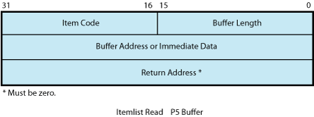
P5 points to a series of item descriptors. Figure 5-4 shows the format for these descriptors. You
cannot repeat the same item code in the same item list.
Figure 5-4 Itemlist Read Descriptor
Table 5-7 lists
the item codes that can be specified in the first longword of the
item descriptors.
Table 5-7 Item Codes for Terminal Driver Itemlist Read Operations
Item Code
Meaning
TRM$_ALTECHSTR
Alternate
echo string. The buffer length word contains the length of the string.
The data address word contains the address of the string. The alternate
echo string is written to the terminal after the first character is
entered.
This item code for character validating read
mode (TRM$K_EM_RDVERIFY) editing only.
TRM$_EDITMODE
Extended editing
modes. The immediate data longword specifies extended editing mode
values. The buffer length word must be zero. The following editing
modes are supported:
TRM$K_EM_DEFAULT
Normal read mode. This is the default if TRM_EDITMODE
is not present in the itemlist.
Escape terminator overflow
size. Specifies the number of bytes that may be used to hold an escape
sequence terminator. This number should be included in P2, the buffer
size argument, in addition to the space required for the data to be
read. Note that this overflow area is for the terminator only; it
is not available for user data.
TRM$_ESCTRMOVR is useful in preventing
partial escape errors, which return SS$_PARTESCAPE. This overflow
buffer ensures that all the characters in an escape sequence terminator
fits in the user buffer, thus eliminating the need for additional
single-character read operations.
TRM$_FILLCHR
A 2-byte value that
indicates the fill and clear character for TRM$K_EM_RDVERIFY. The
first byte of the immediate data longword specifies the clear character;
the second byte specifies the fill character.
This item
code is for character validating read mode (TRM$K_EM_RDVERIFY) editing
only.
TRM$_INIOFFSET
Indicates the character
in the initial string where echoing starts. The immediate data longword
specifies the character.
TRM$_INISTRNG
Specifies
a string to preload into the read buffer (P1). The buffer length word
contains the length of the string. The data longword contains the
address of the string. TRM$_INISTRNG must be specified if the edit
mode is TRM$K_EM_RDVERIFY, and must be the same length as specified
by TRM$_PICSTRNG.
TRM$_MODIFIERS
Read modifiers.
The immediate data longword contains a 32-bit value that specifies
modifiers to read operations. The read operations are defined in $TRMDEF.
The buffer length word must be zero. The following bits are defined:
TRM$M_TM_ARROWS
The terminal interprets the left
and right arrow keys (TRM$K_EM_RDVERIFY mode only). The arrow keys
are not put in the buffer and do not terminate the read. TRM$_ESCTRMOVR
must be greater than or equal to 5.
TRM$M_TM_AUTO_TAB
This bit creates an autotab mode
field (TRM$K_EM_RDVERIFY mode only).
TRM$M_TM_CVTLOW
Lowercase alphabetic characters
(hexadecimal 61 to 7A) are converted to uppercase when transferred
to the user buffer or echoed.
TRM$M_TM_DSABLMBX
The mailbox is disabled for unsolicited
data and for receiving hangup messages.
TRM$M_TM_ESCAPE
A valid ANSI escape sequence is
recognized as a valid delimiter for the read operation.
TRM$M_TM_NOCLEAR
Fill characters are not replaced with
clear characters after a nonfill character occurs (TRM$K_EM_RDVERIFY
mode only).
TRM$M_TM_NOECHO
Characters are not displayed as they
are entered at the keyboard.
TRM$M_TM_NOEDIT
This bit inhibits advanced editing for
this read operation.
TRM$M_TM_NOFILTR
The terminal does not interpret
DEL, Ctrl/U, or Ctrl/R, but passes them to you. This characteristic
explicitly disables line editing.
TRM$M_TM_NORECALL
This bit inhibits command recall
(Ctrl/B) by the terminal driver.
TRM$M_TM_OTHERWAY
This bit sets left-justify fields
to insert mode and right-justify fields to overstrike mode (TRM$K_EM_RDVERIFY
mode only). TRM$M_TM_TOGGLE must equal 1.
TRM$M_TM_PURGE
The type-ahead buffer is purged
before the read operation begins.
TRM$M_TM_R_JUST
This bit creates a right-justified
field (TRM$K_EM_RDVERIFY mode only).
TRM$M_TM_TERM_ARROW
The read operation is
terminated when the left arrow key is pressed at the left margin or
when the right arrow key is pressed at the right margin (TRM$K_EM_RDVERIFY
mode only). TRM$M_TM_ARROWS must be enabled.
TRM$M_TM_TERM_DEL
The read operation is terminated
when the DELETE key is pressed at the left margin (TRM$K_EM_RDVERIFY
mode only).
TRM$M_TM_TOGGLE
Enables Ctrl/A to function as a toggle
key between insert mode and overstrike mode (TRM$K_EM_RDVERIFY mode
only). Left-justify insert mode shifts characters to the right; right-justify
insert mode shifts characters to the left. Shifted characters are
not checked for validity in their new positions.
TRM$M_TM_TIMED
TRM$_TIMEOUT specifies the maximum
time (seconds) that can elapse between characters received from the
terminal; that is, the timeout value for the operation. TRM$M_TM_TIMED
is assumed set if TRM$_TIMEOUT is included in the itemlist. See the
description of IO$M_TIMED in Table 5-6.
TRM$M_TM_TRMNOECHO
The termination character (if
any) is not displayed. There is no formal terminator if the buffer
is filled before the terminator is typed.
All other bits
must be zero.
TRM$_PICSTRNG
Character validation
string. The buffer length word contains the length of the string,
which must be the same as the length specified by TRM$_INISTRNG. The
data address word contains the address of the string. TRM$_PICSTRNG
must be specified if the edit mode is TRM$K_EM_RDVERIFY.
Note that this item code is for character validating read mode (TRM$K_EM_RDVERIFY)
editing only.
The format of the character validation string
is 1 byte per input character. Each byte is a bit mask. The following
values are provided:
Value
Meaning
TRM$M_CV_UPPER
Uppercase alphabetic
TRM$M_CV_LOWER
Lowercase alphabetic
TRM$M_CV_NUMERIC
Numeric (0-9)
TRM$M_CV_NUMPUNC
Numeric punctuation (+ - .)
TRM$M_CV_PRINTABLE
Printable ASCII character
TRM$M_CV_ANY
Any character
If no values are set, the
corresponding character specified by TRM$_INISTRNG is used. Appendix C lists the multinational character
set.
TRM$_PROMPT
Specifies
a prompt string. The buffer length word contains the length of the
prompt. The data address word contains the address of the prompt string.
See “Read” for information on how carriage control specifiers in a prompt
string are handled.
TRM$_TERM
The buffer
length word determines the format of the nondefault terminator mask.
If the buffer length word is zero, then the data longword is used
as a short form mask. If the buffer length word is nonzero, then a
mask n bytes long is available at the specified
address.
TRM$_TIMEOUT
Read timeout. See the
description of IO$M_TIMED in Table 5-6.
5.3.1.4 Read Verify Function
When using the read verify function,
the terminal driver performs input validation based on character attributes.
(Read verification bypasses the optionally specified termination mask
(TRM$_TERM).) Validation is performed one character at a time as data
is entered. Invalid characters are not echoed, and cause the read
operation to complete. It is then up to the application program to
handle the error appropriately.
The initial string describes the initial contents
of the input field. This string may consist of data and marker characters.
The clear character is displayed on the screen for each occurrence
of the fill character in the initial string buffer.
The picture string is a string of bytes where
each byte corresponds to one character of the field being entered.
Each byte specifies a mask of legal character types for that character
position. If the byte is left as zero, then that position is a marker
character, and the character from the initial string is echoed for
that position.
For left-justified fields, the prompt data is
output to the terminal, followed by an optional number (TRM$_INIOFFSET)
of initial string characters. Leading marker characters are always
output following the prompt, leaving the cursor at the leftmost data
position. As each character is entered, it is validated and then echoed,
advancing the cursor position. Additional marker characters are skipped
as they are encountered. If an input character fails the validation,
the read operation is completed with the invalid character as the
terminator.
For right-justified fields, the prompt is output
and is followed by the initial string. (In general, TRM$_INIOFFSET
is set to the length of TRM$_INISTRNG for right-justified fields.)
The cursor position remains one position to the right of the initial
string. For proper operation, right-justified fields cannot have mixed
picture definitions. After each character is input, the entire prompt
and input fields are output. Therefore, the prompt should include
a cursor positioning escape sequence.
The definition of full field is different for
left- and right-justified read operations. For left-justified fields,
full field is detected when the character corresponding to the last
nonmarker position in the picture string has been entered. For right-justified
fields, full field is detected when a character other than the fill
character is shifted into the leftmost, nonmarker position in the
field.
If the modifier TRM$M_TM_AUTO_TAB is set in TRM$_MODIFIERS,
then detection of a full field terminates the read operation. In the
event of autotab termination, the terminator character in the IOSB
is null. If the autotab option is not selected, then termination occurs
when one more character is typed to a full field. Applications can
detect this condition when the terminating character index is one
character beyond the end of the field. The extra character is reported
as the terminator. In a left-justified field, the IOSB index to the
terminator is zero-based; in a right-justified field, this index is
one-based.
If a read verify function is interrupted by an
asynchronous write operation, the read verify is completed with status
SS$_OPINCOMPL.
No line editing functions other than the delete
character function are supported for read verify.
5.3.2 Write
Write operations
display the contents of a user-specified buffer on the associated
terminal. The operating system provides the following write I/O functions,
which are listed with their function codes:
IO$_WRITEVBLK—Write
virtual block
IO$_WRITELBLK—Write
logical block
IO$_WRITEPBLK—Write
physical block
The write function codes can take the following
device- or function-dependent arguments:
P1—The starting
virtual address of the buffer that is to be written to the terminal.
P2—The number of
bytes that are to be written to the terminal. (The system generation
parameter, MAXBUF, and the terminal driver limit the maximum size
of the buffer. The terminal driver only functions with buffer sizes
less than 32718 bytes.)
P4—Carriage control
specifier except for write physical block operations. (Write function
carriage control is described in “Write Function Carriage Control”.)
P3, P5, and P6 are not meaningful for terminal
write operations.
In write virtual block and write logical block
operations, the buffer (P1 and P2) is formatted for the selected terminal
and includes the carriage control information specified by P4.
Unless TT$M_MECHFORM is specified, multiple line
feeds are generated for form feeds. The number of line feeds generated
depends on the current page position and the length of the page. By
producing a carriage return after the last line feed, a form
feed also moves the cursor to the left margin. Multiple spaces are
generated for tabs if the characteristics of the selected terminal
do not include TT$M_MECHTAB (this does not apply to write physical
block operations). Tab stops occur every eight characters or positions.
CTDRIVER and Buffered Output
CTDRIVER, a component of the SET HOST facility, buffers
output from remote terminals in order to package multiple output requests
into a single network transfer. As a result, control is returned early
to the user with a status of SS$_NORMAL when the output buffer has
been filled and successfully queued.
Note that this output might not be displayed if
the user enters an abort character or a Ctrl/O.
5.3.2.1 Function Modifier Codes for Write QIO Functions
Five function modifiers can be specified with
IO$_WRITEVBLK, IO$_WRITELBLK, and IO$_WRITEPBLK. Table 5-8 lists these function modifiers. All write function
modifiers are supported for LAT devices.
Table 5-8 Write QIO Function Modifiers for the Terminal Driver
Code
Consequence
IO$M_BREAKTHRU
Allows breakthrough read
regardless of the current active state.
IO$M_CANCTRLO
Turns off Ctrl/O (if
it is in effect) before the write operation. Otherwise, the data cannot be displayed.
IO$M_ENABLMBX
Enables use of the mailbox
associated with the terminal for notification that unsolicited data is available.
IO$M_NOFORMAT
Allows you to specify
write functions without interpretation or format; in effect, the terminal
line is in a temporary PASTHRU mode.
IO$M_REFRESH
If a read operation is interrupted
by a write operation (by either a write breakthrough[1] or any other type of write), the terminal displays the current read
data when the read function is restarted.
[1] Any interruption caused by the execution of the $BRDCST or the
$BRKTHRU system service broadcasting messages to terminals is referred
to as a “write breakthrough.”
5.3.2.2 Write Function Carriage Control
The P4 argument is a longword that specifies carriage
control. Carriage control determines the next printing position on
the terminal. P4 is ignored in a write physical
block operation. Figure 5-5 shows
the P4 longword format.
Figure 5-5 P4 Carriage Control Specifier
Only bytes 0, 2, and 3 in the longword are used.
Byte 1 is ignored. If the low-order byte (byte 0) is not 0, the contents
of the longword are interpreted as a FORTRAN carriage control specifier. Table 5-9 lists the possible byte
0 values (in hexadecimal) and their meanings.
Table 5-9 FORTRAN Write Function Carriage Control
Byte 0 Value (hexadecimal)
ASCII Character
Meaning
20
(space)
Single-space carriage
control (sequence: carriage-return/line-feed combination, print buffer
contents, return[1]).
Page eject carriage control (sequence:
form feed, print buffer contents, return).
2B
+
Overprint carriage control; allows
double printing for emphasis or special effects (sequence: print buffer
contents, return).
24
$
Prompt carriage control (sequence:
carriage-return/line-feed combination, print buffer contents).
All other values
Same as ASCII space character: single-space carriage control.
[1] A carriage-return/line-feed combination is a carriage return
followed by a line feed.
If the low-order byte (byte 0) is 0, bytes 2 and
3 of the P4 longword are interpreted as the prefix and postfix carriage
control specifiers. The prefix (byte 2) specifies the carriage control
before the buffer contents are printed. The postfix (byte 3) specifies
the carriage control after the buffer contents are printed. The sequence
is as follows:
Prefix carriage control
Print
Postfix carriage control
The prefix and postfix bytes, although interpreted
separately, use the same encoding scheme. Table 5-10 shows this encoding scheme in hexadecimal.
With several exceptions, Figure 5-6 shows the prefix and postfix hexadecimal coding
that produces the carriage control functions listed in Table 5-9. Prefix and postfix
coding provides an alternative way to achieve these controls.
In the first example in Figure 5-6, the prefix/postfix hexadecimal coding for a
single-space carriage control (carriage-return/line-feed combination,
print buffer contents, return) is obtained by placing the value 1
in the second (prefix) byte and the sum of the bit 7 value (80) and
the return value (D) in the third postfix byte.
Table 5-10 Write Function Carriage Control (P4 byte 0 = 0)
Prefix/Postfix Bytes
(Hexadecimal)
Bit 7
Bits 0—6
Meaning
0
0
No carriage control is specified (NULL).
0
1—7F
Bits 0 through 6 are a count of carriage-return/line-feed
combinations.
Bit 7
Bit 6
Bit 5
Bits 0—4
Meaning
1
0
0
0—1F
Output the single ASCII control
character specified by the configuration of bits 0 through 4 (7-bit
character set).
1
1
0
0—1F
Output the single ASCII control
character specified by the configuration of bits 0 through 4, which
are translated as ASCII characters 128 through 159 (8-bit character
set; see Appendix C).
1
1
1
0—1F
Reserved.
Figure 5-6 Write Function Carriage Control (Prefix and Postfix Coding)
5.3.3 Set Mode
Set mode operations affect
the operation and characteristics of the associated terminal line.
The operating system provides two types of set mode functions: set
mode and set characteristics.
The set mode function affects the mode and temporary
characteristics of the associated terminal line. Set mode is a logical
I/O function and requires no privilege. (If you do not have LOG_IO
or PHY_IO privilege, the terminal driver does not accept a set mode
request to a terminal that does not have the extended terminal characteristic
TT2$M_SETSPEED, even if no request for a change of speed is made.
Privilege is not required if TT2$M_SETSPEED is set but no attempt
to change the speed is made.) The following function code is provided:
IO$_SETMODE
The set characteristics function affects the permanent
characteristics of the associated terminal line. Set characteristics
is a physical I/O function and requires the privilege necessary to
perform physical I/O. The following function code is provided:
IO$_SETCHAR
The set mode and set characteristics functions
take the following device- or function-dependent arguments if no function
modifiers are specified:
P1—Address of characteristics
buffer
P2—Length of characteristics
buffer (default length is 8 bytes, maximum is 16 bytes)
P3—Speed specifier
(bits 0 through 7 = transmit; 8 through 15 = receive)
P4—Fill specifier
(bits 0 through 7 = CR fill count; bits 8 through 15 = LF fill count)
P5—Parity flags
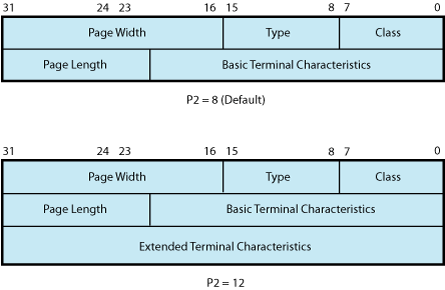
The P1 argument points to a variable-length block,
as shown in Figure 5-7. With
the exception of terminal characteristics, the contents of the block
are the same for both the set mode and set characteristics functions.
Figure 5-7 Set Mode and Set Characteristics Buffers
In the buffer, the device class is DC$_TERM, which
is defined by the $DCDEF macro. The terminal type is defined by the
$TTDEF macro; for example, TT$_LA36. The page width is a value in
the range of 1 through 511. The page length is a value in the range
of 0 through 255. Table 5-4 lists
the values for terminal
characteristics. Table 5-5 lists
the extended terminal characteristics. Characteristics values are
defined by the $TTDEF, $TT2DEF, and $TT3DEF macros.
NOTE: Make sure that the selected device is a terminal
before performing any set mode function, particularly when using SYS$INPUT
or SYS$OUTPUT.
The P3 argument defines the device speed, such
as TT$C_BAUD_300. The low eight bits specify the transmit speed, and
the high eight bits specify the receive speed. If no receive speed is specified, the indicated transmit speed is used for both
transmitting and receiving. If neither the transmit nor the receive
speed is specified (P3 = 0), the baud rate is not changed. The terminal
driver ignores the receive speed bits for interfaces that do not support
split-speed operation. Though speeds up to 115.2 K baud can be specified,
not all controllers support all speed combinations. See the associated
hardware documentation to determine which speeds are supported by
your controller.
P4 contains fill counts for the carriage-return
and line-feed characters. Bits 0 through 7 specify the number of fill
characters used after a carriage return. Bits 8 through 15 specify
the number of fill characters used after a line feed.
P4 is applicable only if TT$M_CRFILL or TT$M_LFFILL
is specified as a terminal characteristic for the current QIO request;
see Table 5-4.
Several parity flags can be specified in the P5
argument:
TT$M_ALTRPAR—Alter
parity. If set, check the state of TT$M_PARITY and TT$M_ODD and, if
indicated, change the parity. Otherwise, ignore these bits.
TT$M_PARITY—Enable
parity on terminal line if set, disable if clear.
TT$M_ODD—Parity
is odd if set.
TT$M_ALTDISPAR—Alter
dismiss parity errors. If set, check the state of TT$M_DISPARERR.
TT$M_DISPARERR—Dismiss
parity errors. If this mode is set, a character with a parity error
is passed to the reader. An error message is not reported.
NOTE: If parity is enabled, the DZ11 generates a parity
check bit to detect parity mismatch. Unless TT$M_DISPARERR is enabled,
parity errors that occur during an I/O read operation are fatal to
the operation. Parity errors that occur on input characters (that
is, keys pressed on the keyboard) when no I/O operation is in progress
might result in a character loss.
TT$M_BREAK—Generate
a break if set. The break is in effect until this bit is turned off.
TT$M_BREAK is supported by the LTDRIVER for terminal servers that
support the break capability, such as the DECserver 200 and DECserver
500. However, in the case of LAT terminals, the terminal server controls
the duration of the break.
TT$M_ALTFRAME—If
set, the four low-order bits of P5 become the frame size. Note that
the frame size is for data bits only and is exclusive of parity. TT$M_ALTFRAME
is supported for frame sizes of 7 and 8 for LAT devices.
To take the existing parity settings, modify them,
and use them in the set mode or set characteristic function, move
the byte starting at the second nibble of the buffer that is going
to be used in the P5 argument. For example, the following instructions
change the parity from even to odd:
Application programs that change terminal characteristics should perform the following steps:
Use the IO$_SENSEMODE
function to read the current characteristics.
Modify the characteristics.
Use the set mode function
to write back the results.
If the characteristic
is intended to be reset when the image exits, the application must
perform this operation.
Failure to follow this sequence results in clearing
any previously set characteristic.
Two stop bits are used only for data rates less
than or equal to 150 baud; higher data rates default to one stop bit.
The set mode and set characteristics functions
can take the enable Ctrl/C AST, enable Ctrl/Y AST, enable out-of-band
AST, hangup, set modem, broadcast, and loopback function modifiers
that are described in the following sections.
NOTE: If an attempt is made to turn on TT2$V_FALLBACK
for a disconnected virtual terminal
(_VTAx:) or if the Terminal Fallback facility has not been activated,
the status code SS$_BADPARAM is returned. For more information on
TFF, see the OpenVMS Terminal Fallback Utility Manual (available on the Documentation CD-ROM).
5.3.3.1 Hangup Function Modifier
The hangup function disconnects a terminal that
is on a dialup line. (Dialup lines are described in “Set Mode”.) The following
combinations of function code and modifier are provided:
IO$_SETMODE!IO$M_HANGUP
IO$_SETCHAR!IO$M_HANGUP
The hangup function modifier takes no arguments.
SS$_NORMAL is returned in the I/O status block.
NOTE: For remote terminals, the hangup function breaks
the network connection to the local system, ending the remote terminal
session.
5.3.3.2 Enable Ctrl/C AST and Enable Ctrl/Y AST Function Modifiers
Both set mode functions can take the enable Ctrl/C AST and enable Ctrl/Y AST function modifiers.
These function modifiers request the terminal driver to queue an AST
for the requesting process when you press Ctrl/C or Ctrl/Y. The following
combinations of function code and modifier are provided:
IO$_SETMODE!IO$M_CTRLCAST—Enable
Ctrl/C AST
IO$_SETMODE!IO$M_CTRLYAST—Enable
Ctrl/Y AST
These function code modifier pairs take the following
device- or function-dependent arguments:
P1—Address of the
AST service or 0 if the corresponding AST is disabled
P2—AST parameter
P3—Access mode
to deliver AST (maximized with caller's access mode)
If the respective enabling is in effect, pressing
Ctrl/C or Ctrl/Y gains the attention of the enabling process (see Table 5-1).
Enable Ctrl/C and Ctrl/Y AST are one-time enabling
function modifiers. After the AST occurs, it must be explicitly reenabled
by one of the two function code combinations before an AST can occur
again. This function code is also used to disable the AST. The function
is subject to AST quotas.
You can have more than one Ctrl/C or Ctrl/Y enabled; pressing
Ctrl/C, for example, results in the delivery of all Ctrl/C ASTs. ASTs
are queued and delivered to the user process on a first-in/first-out
basis for each access mode. However, ASTs are processed in the reverse
order of the Ctrl/C AST or Ctrl/Y AST requests that have been issued
to the terminal driver (on a last-in/first-out basis).
If no enable Ctrl/C AST is present, the holder
of an enable Ctrl/Y AST receives an AST when Ctrl/C is pressed; carriage-return/line-feed
combination, Ctrl/Y, and Return are echoed.
Figure 5-9 shows the relationship of Ctrl/C and Ctrl/Y with the out-of-band
function. If Ctrl/C or Ctrl/Y is an enabled out-of-band character, any out-of-band
ASTs specified for this character are delivered. If IO$M_INCLUDE function
modifier is included in the out-of-band AST request for this character,
an enabled Ctrl/C or Ctrl/Y AST is also delivered.
Enable Ctrl/C AST requests are flushed by the
Cancel I/O on the Channel ($CANCEL) system service. Enable Ctrl/Y
AST requests are flushed by the Deassign I/O Channel ($DASSGN) system
service.
Ctrl/Y is normally used to gain the attention
of the command interpreter and to input special commands such as DEBUG,
STOP, and CONTINUE. Programs that are run from a command interpreter
should not enable Ctrl/Y. Because ASTs are delivered on a first-in/first-out
basis, the command interpreter's AST routine gets control first,
and might not allow the program's AST to be delivered at all.
Programs that require the use of Ctrl/Y should use the LIB$DISABLE_CTRL
RTL routine to disable DCL recognition of Ctrl/Y.
See Example 5-4 for a programming example that demonstrates
Ctrl/Y and Ctrl/C handling under OpenVMS.
The set modem function modifier is used in maintenance operations to allow a process
to activate and deactivate modem control signals. Both set mode and
set characteristics functions can take the set modem function modifier.
The following combinations of function code and modifier are provided:
IO$_SETMODE!IO$M_SET_MODEM!IO$M_MAINT
IO$_SETCHAR!IO$M_SET_MODEM!IO$M_MAINT
NOTE: For LAT devices, the set modem field for maintenance
operations of the IO$M_SET_MODEM!IO$M_MAINT function modifier is unsupported
and may return unpredictable results.
These function code modifier pairs take the following
device- or function-dependent argument:
P1—The address
of a quadword block that specifies which modem control signals to
activate or deactivate
The modem on and modem off fields, in combination
or separately, can specify one or more of the following values:
TT$M_DS_RTS—Request
to send (RTS)
TT$M_DS_DTR—Data
terminal ready (DTR)
Figure 5-8 Set Mode P1 Block
TT$M_DS_SECTX—Transmitted
backward channel data (Sec Txd)
The $TTDEF macro defines the values for these
values. These values can only be specified if the terminal characteristic
TT$M_MODEM is not set. Otherwise, an error (SS$_ABORT) occurs.
NOTE: The set modem function is not supported for remote
terminals. The status SS$_DEVREQERR is returned in the I/O status
block.
Because the DMF32 does not provide the secondary
transmitted data signal (Sec Txd), the driver sets the secondary request
to send the signal. Users should connect a jumper cable between pins
14 and 19 on the DMF32.
5.3.3.4 Loopback Function Modifier
The loopback function modifier is used in maintenance
operations to place the terminal line in a hardware loopback mode. Data transmitted
to a line in this mode is returned as receive data. If the controller
does not support loopback mode or the terminal line has the TT$M_MODEM
characteristic set, an error status (SS$_ABORT) is returned. Both
set mode functions can take the loopback function modifier.
NOTE: The loopback function is not supported for remote
terminals. The status SS$_DEVREQERR is returned in the I/O status
block.
The following combinations of function code and
modifier are provided:
IO$_SETMODE!IO$M_LOOP!IO$M_MAINT
IO$_SETCHAR!IO$M_LOOP!IO$M_MAINT
Data transmitted in the loopback mode should only
be written in records less than or equal to the size of the type-ahead
buffer (see “Type-Ahead Feature”). Programs that use the loopback function modifier should incorporate
a 1-second delay to allow the controller to enable the loopback mode
after the request is posted. Write requests should also include the
IO$M_NOFORMAT function modifier to prevent terminal driver from formatting input or output data.
The operating system provides another function
modifier to reset a terminal line previously placed in loopback mode.
The following combinations of function code and modifier are provided:
IO$_SETMODE!IO$M_UNLOOP!IO$M_MAINT
IO$_SETCHAR!IO$M_UNLOOP!IO$M_MAINT
Programs that use the unloop function modifier
should incorporate a 1-second delay to allow the controller to reset
the loopback mode after the request is posted.
NOTE: IO$M_LOOP and IO$M_UNLOOP are not supported for
LAT devices.
5.3.3.5 Enable Out-of-Band AST Function Modifier
The enable out-of-band AST function modifier requests
that the terminal driver queue an AST for the requesting
process when you enter any one of 32 control characters. The following combinations
of function code and modifier are provided:
IO$_SETMODE!IO$M_OUTBAND—Enable
out-of-band AST
IO$_SETCHAR!IO$M_OUTBAND—Enable
out-of-band AST
These function code modifier pairs take the following
device- or function-dependent arguments:
P1—Address of the
AST service or 0 if the AST entered on this channel is to be canceled.
(The AST parameter is the out-of-band character.)
P2—Address of a
character mask with the same format as the short form terminator mask
(see “Read Function Terminators”).
P3—Access mode
to deliver AST (maximized with the caller's access mode).
The IO$_SETMODE!IO$M_OUTBAND function can optionally
take the following function modifiers:
IO$M_INCLUDE—Include
the character typed in the data stream.
IO$M_TT_ABORT—Allow
current read and write operations to be aborted. (The IOSB for aborted
operations returns the status SS$_CONTROLC.)
If an out-of-band AST is in effect, pressing any
control character specified in the P2 mask gains the attention of
the enabling process. Figure 5-9 shows the relationship of the out-of-band function with some of
the control characters.
You can have only one out-of-band AST enabled
per channel.
Out-of-band ASTs are repeating ASTs; they continue
to be delivered until specifically disabled. Out-of-band AST enables
are flushed by the Cancel I/O on Channel ($CANCEL) system service.
Figure 5-9 Relationship of Out-of-Band Function with Control Characters
5.3.3.6 Broadcast Function Modifier
The broadcast function modifier allows you to turn on or turn off
selected broadcast requester identifiers (IDs). The following combination
of function code and modifier is provided:
IO$_SETMODE!IO$M_BRDCST
This
function code modifier pair takes the following device- or function-dependent
arguments:
P1—A buffer that
contains the bits that specify the requester IDs to be broadcast
P2—The length of
the P1 buffer (default is 8 bytes)
The first longword of P1 is reserved for use by
HP facilities, as shown in Table 5-11. The symbols are defined in the system macro library ($BRKDEF).
The second longword is for customer use to specify selected bits.
If any bit is set in the P1 buffer, that particular requester ID is
turned off for broadcast.
Table 5-11 Broadcast Requester IDs
Bit
Meaning
BRK$C_DCL
Disables broadcasts by
Ctrl/T
BRK$C_GENERAL
Disables broadcasts by
the DCL command REPLY and the SYS$BRDCST system service
BRK$C_MAIL
Disables broadcasts by
the Mail utility
BRK$C_PHONE
Disables broadcasts by
the Phone utility
BRC$C_QUEUE
Disables broadcasts about
batch and print queues
BRK$C_SHUTDOWN
Disables broadcasts about
system shutdown
BRK$C_URGENT
Disables broadcasts labeled
URGENT by the REPLY command
BRK$C_USERn
Disables broadcasts
by images associated with the specified value; n can be any decimal integer between 1 and 16
5.3.4 LAT Port Driver QIO Interface
The LAT port driver (LTDRIVER)
accommodates I/O requests from application programs for connections
to remote devices on one or more terminal servers; for connections
to remote services; and for configuring LTDRIVER and retrieving configuration
information about LTDRIVER. A remote device, such as a printer, can
be shared in a LAT configuration. Before an application program can
access a remote device, the system manager must create logical devices
and map them to physical devices connected to terminal servers. Creating
and mapping these logical devices can be done either with the LAT
Control Program (LATCP) utility or with a $QIO request from a program
that has OPER privilege. Once mapped, application programs can establish
and terminate connections to these remote devices.
This section describes the capabilities of the
QIO interface to the LAT port driver (LTDRIVER). The QIO interface
allows application programs to access and modify information contained
in the LTDRIVER data structures and to initiate events and obtain
status information. You must use these QIO functions to establish
a connection to a remote device or service from an application program.
HP does not support any other methods of connection.
The LTDRIVER responds to TEST SERVICE commands
issued at terminal servers that support the TEST SERVICE command,
such as the DECserver 200 and DECserver 500 servers.
LAT devices can use all read and write function
modifiers listed for the terminal driver function codes except those
modifiers that apply to modems (see “Read” and “Write”).
The operating system does not support the following
set mode or set characteristics function code modifiers for LAT devices:
IO$M_LOOP
IO$M_UNLOOP
TT$M_ALTRPAR
TT$M_ALTFRAME
TT$M_MODEM
TT$M_READSYNC
TT2$M_SETSPEED
With LAT devices, the terminal server, rather
than the host, handles flow control to the physical device. A separate
flow control mechanism exists between the server and the host.
5.3.4.1 LAT Port Types
QIO functions can be used to create the following
LAT port types:
Application Port. This
type of port can be used to connect to a remote device (typically
a printer) on a terminal server or to a dedicated port on another
LAT service node. This is the default port type. See “Programming Application Ports” for a description
of programming an application port.
Dedicated Port. This type
of port specifies that the logical port on your node is dedicated
to an application service. When users on a terminal server (or on
another node that supports outgoing connections) request a connection
to this service name, they are connected to a dedicated port. See “Programming Application Services and Dedicated Ports” for a description
of programming a dedicated port and application service.
Forward Port. This type
of port is used for outgoing LAT connections (to remote services)
and is created by assigning a channel to the LAT template device _LTA0:
with the $ASSIGN system service.
QIO functions
can also be used to configure and read information about these ports;
for more information:
See “Programming Forward Ports” for a description of programming
a forward port in order to make a connection to a LAT service
5.3.4.2 LAT Port Driver Functions
The operating system provides the following combinations
of function code and modifier:
IO$_TTY_PORT!IO$M_LT_CONNECT.
Requests that the LAT port driver make a connection to a remote device
on a server (or dedicated port on another LAT service node) or to
a remote service, depending on whether the port is an application
port or a forward port respectively. For dedicated ports, this QIO
completes when an incoming connection to the port is established.
See “Programming Application Ports” for
a description of programming an application port, “Programming Application Services and Dedicated Ports” for a description
of programming a dedicated port, and “Programming Forward Ports” for a description of programming
a forward port.
IO$_TTY_PORT!IO$M_LT_DISCON.
Depending on the port type, requests that the LAT port driver terminate
the LAT connection to the remote device, service, or local application
service. IO$M_FLUSH_DATA can be specified in the P2 argument to IO$M_LT_DISCON.
The flush flag indicates that any data not delivered to the remote
device is to be flushed when the disconnect is issued.
IO$_TTY_PORT!IO$M_LT_SETMODE.
Requests that the LAT port driver create or configure a LAT entity.
See “Creating and Configuring LAT Entities” for more information.
IO$_TTY_PORT!IO$M_LT_SENSEMODE.
Requests that the LAT port driver return configuration information
about a LAT entity. See “Obtaining Information About LAT Entities” for more information.
5.3.4.3 Creating and Configuring LAT Entities
The LAT SETMODE $QIO function (IO$_TTY_PORT!IO$M_LT_SETMODE)
is used to create, delete, and modify LAT nodes, services, ports,
and links.
Creation, deletion, or modification of any entity
requires the OPER privilege.
The LAT SETMODE $QIO function accepts four arguments:
P1, P2, P3, and P4. P1 is the address of an item list; P2 is the length
of this item list.
P3 specifies the type of entity to which the SETMODE
operation applies. The entity type can be one of five types:
Node (LAT$C_ENT_NODE).
Only the local node name may be specified, with the exception of a
SETMODE itemlist containing no item codes other than LAT$_ITM_COUNTERS.
Service (LAT$C_ENT_SERVICE).
Only local service names may be specified, with the exception of a
SETMODE itemlist containing no item codes other than LAT$_ITM_COUNTERS.
Link (LAT$C_ENT_LINK).
The data link associated with the LAN.
Port (LAT$C_ENT_PORT).
Queue Entry (LAT$C_ENT_QUEUE_ENTRY).
Indicates queue entry entities. When this entity is used, the only
valid SETMODE operation is delete.
The value for the entity type occupies the low-order
16 bits (bits 0--15) of the P3 parameter. For all four entity types,
bits 16--19 are used as a status field to indicate the expected current
status of the entity. These bits are used to decide whether the entity
needs to be created before its characteristics are set. The possible
values for this field are:
LAT$C_ENTS_OLD—The
entity must already exist. An SS$_NOSUCHDEV error is returned if the
entity does not exist.
LAT$C_ENTS_NEW—The
entity must be created. An SS$_DUPLNAM error is returned if the entity
already exists.
LAT$C_ENTS_UNK—If
the entity does not exist, it is created. If it does exist, its characteristics
are modified.
LAT$C_ENTS_DEL—If
the entity exists, delete it. Otherwise, an SS$_NOSUCHDEV error is
returned and the item list is not used.
P4 may contain the address of an entity name string
descriptor. If this parameter is omitted (contains a 0 or the address
of a descriptor that points to an empty buffer), a default may be
used in some cases. The defaults for each entity type are as follows:
LAT$C_ENT_NODE—The
local node.
LAT$C_ENT_SERVICE—No
default; you must specify the service name.
LAT$C_ENT_LINK—The
string LAT$LINK.
LAT$C_ENT_PORT—The
device name associated with the currently assigned channel (the CHAN
parameter of the $QIO function).
SETMODE can return the following status codes:
SS$_NOPRIV—No privilege
to complete the desired operation.
SS$_ACCVIO—Part
of the argument list or itemlist is not addressable.
SS$_BADPARAM—One
of the parameters in the itemlist is in error. If this value is returned,
the second longword of the IOSB contains the item code of the parameter
in error.
SETMODE Item Codes
Each item in the itemlist consists of a one-word
(16-bit) item code, followed by a value associated with the item.
Item codes in which the bit named LAT$V_STRING
is zero take a longword value. The associated value is contained in
the longword immediately following the item code in the itemlist.
Item codes in which this bit is 1 take a counted string for their
value. The byte immediately following the item code contains a byte
count, which describes the length of the string that immediately follows
it.
If you set bit LAT$V_CLEAR in the item code to
1, the current value associated with the item code is cleared or set
to its default value. In this case, the actual value specified in
the itemlist is ignored, although the byte count field skips to the
next item in the itemlist.
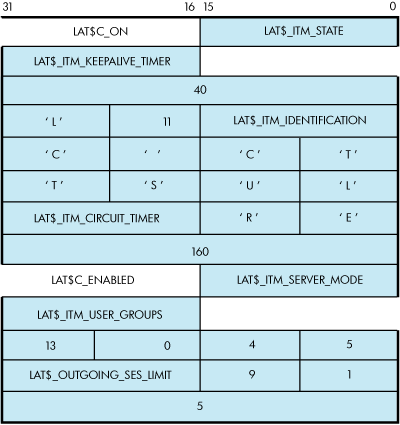
Figure 5-10 shows an example of a SETMODE itemlist.
Figure 5-10 Example SETMODE Itemlist
This SETMODE itemlist is the P1 parameter for
a $QIO SETMODE function on the local node. P4 is omitted, and P3 is
#LAT$C_ENT_NODE!$C_ENTS_OLD@16>. P2 is the length of the itemlist
(52). A $QIO SETMODE function for this itemlist would perform the
following operations:
Set the state of the node
to on.
Set the LAT keepalive
timer to 40 seconds.
Set the node identification
to LTC CLUSTER.
Set the LAT circuit timer
to 160 milliseconds.
Enable LAT outbound connections.
Turn on user groups 2,
8, 10, 11, 12, 16, and 19. LAT$_ITM_USER_GROUPS is represented by
a bit field.
Set the outgoing session
limit to five sessions.
For each entity type, only a subset of item codes
may be set. Table 5-12 lists the
item codes that may be set for the LAT$C_ENT_NODE entity type.
Table 5-12 LAT$C_ENT_NODE Item Codes
Item Code
Meaning
LAT$_ITM_STATE
Operating
state of the LAT protocol. The following values are allowed:
LAT$C_OFF
Turns off LAT protocol processing. No new connections
allowed in either direction. Existing connections are terminated immediately.
This is the default.
LAT$C_SHUT
Disallows new LAT connections in either
direction. Existing connections are allowed to remain active.
LAT$C_ON
Turns on LAT protocol processing.
LAT$_ITM_CIRCUIT_TIMER
Circuit timer value
in milliseconds. Valid values are 10 to 1000 milliseconds. The default
is 80 milliseconds.
LAT$_ITM_CPU_RATING
CPU rating.
Valid values are 0 to 100. If this value is 0, then the CPU rating
value is not used in the rating calculation. See the HP OpenVMS System Management Utilities Reference Manual for a complete description of this feature.
LAT$_ITM_DEVICE_SEED
Overrides the default
lower boundary for new LTA devices. Valid values are 0 to 9999; the
default is 0. See the HP OpenVMS System Management
Utilities Reference Manual for more information on this
feature.
LAT$_ITM_KEEPALIVE_TIMER
Keepalive
timer value in seconds. Valid values are 10 to 255 seconds. The default
is 20 seconds.
LAT$_ITM_MULTICAST_TIMER
Multicast
timer value in seconds. Valid values are 10 to 180 seconds. The default
is 60 seconds.
LAT$_ITM_NODE_LIMIT
Maximum number
of nodes in LAT database. The default is 0, where the maximum is determined
by system resources.
LAT$_ITM_RETRANSMIT_LIMIT
LAT retransmit
limit. Valid values are 4 to 120 retransmissions. The default is 8
retransmissions.
LAT$_ITM_SERVER_MODE
Controls whether the node
allows the use of the MASTER side of the LAT protocol for outbound
connections. Valid values are:
LAT$C_DISABLED
Server mode disabled (this is
the default).
LAT$C_ENABLED
Server mode enabled.
LAT$_ITM_SERVICE_RESPONDER
Indicates whether
the node is to respond to service inquiries originating from a remote
system. These inquiries are not necessarily directed at services being
offered by the node. See the HP OpenVMS System
Management Utilities Reference Manual for a complete description
of this feature. Valid values are:
LAT$C_DISABLED
Service responder disabled (this
is the default).
LAT$C_ENABLED
Service responder enabled.
LAT$_ITM_OUTGOING_SES_LIMIT
Maximum number of
outgoing LAT sessions. A value of 0, which is the default, indicates
that the limit is determined by system resources.
LAT$_ITM_INCOMING_SES_LIMIT
Maximum number
of interactive LAT sessions. A value of 0, which is the default, indicates
that the limit is determined by system resources.
LAT$_ITM_CONNECTIONS
Controls whether
inbound connections can be accepted. Valid values are:
LAT$C_DISABLED
Inbound connections disabled.
LAT$C_ENABLED
Inbound connections enabled (this is the default).
LAT$_ITM_NODE_NAME
Causes the
LAT node name to be set to the given name. This item code may be specified
only if the entity status field of the P3 parameter is LAT$C_ENTS_NEW;
otherwise, a LAT$_ENTNOTFOU error results.
LAT$_ITM_IDENTIFICATION
Node identification
string. The default is the translation of SYS$ANNOUNCE.
LAT$_ITM_SERVICE_GROUPS
Specifies
a default service group code bit mask. This mask is then used when
creating new local services. The default is group code 0 enabled and
all others disabled when the LAT software is initialized.
Note that the use of the LAT$V_CLEAR bit is an exception for this
parameter code. If you clear bit LAT$V_CLEAR, group codes corresponding
to the group code mask, as specified in the itemlist, are set. Alternatively,
if you set LAT$V_CLEAR, group codes corresponding to the group code
mask, as specified in the itemlist, are cleared.
LAT$_ITM_USER_GROUPS
LAT group
codes to be used when attempting outbound connections using the MASTER
side of the LAT protocol. The default is all group codes disabled
when the LAT software is initialized.
Note that the use
of the LAT$V_CLEAR bit is an exception for this parameter code. If
you clear bit LAT$V_CLEAR, group codes corresponding to the group
code mask, as specified in the itemlist, are set. Alternatively, if
you set LAT$V_CLEAR, group codes corresponding to the group code mask,
as specified in the itemlist, are cleared.
LAT$_ITM_COUNTERS
Node counters
block. Allows for zeroing of all node counters. This item code may
be specified only if the entity status field of the P3 parameter is
LAT$C_ENTS_OLD and the LAT$V_CLEAR bit is set. Violating either of
these two rules results in a returned status of SS$_BADPARAM.
LAT$_ITM_MAXIMUM_UNITS
Maximum unit
number. Sets the highest value for a LTA unit number. Must be between
1 and 9999; defaults to 9999.
Indicates maximum number of outstanding, unprocessed
service announcement messages allowed on LATACP's queue. If this
limit is ever reached, subsequent service announcement messages are
not delivered or processed by LATACP.
Indicates maximum number of outstanding, unprocessed solicit
information messages allowed on LATACP's queue. If this limit
is ever reached, subsequent solicit information messages are not delivered
or processed by LATACP.
Indicates returned service class bit mask for supported
service classes on node. It is returned for both local and remote
nodes. If service class 1 is enabled, then bit 1 is set in this mask.
When bit setting equals 1, this indicates the corresponding service
class for that bit is enabled. That is, when bit 3 equal 1, then service
class 3 is enabled.
LAT$_ITM_LARGE_BUFFERS
Indicates
in Boolean logic whether or not the LAT software is using large packet
support by default.
LAT$_ITM_ANNOUNCEMENTS
Indicates in Boolean
logic whether or not the LAT software is transmitting LAT service
advertisement messages.
Service counters
block. Allows for zeroing of all service counters. This item code
may be specified only if the entity status field is LAT$C_ENTS_OLD
and the LAT$V_CLEAR bit is set. Violating either of these two rules
results in a returned status of SS$_BADPARAM.
Indicates that if a value of LAT$C_ENABLED is indicated, then
the service is password protected. Indicates that if a value of LAT$C_DISABLED
is indicated, then the service is not password protected.
Indicates a subblock contained in an itemlist, which has a list of
limited ports associated with the named service. This subblock may
be repeated several times; that is, once for each limited LAT device
associated with the specified service.
Table 5-14 lists
the item codes that may be set for the LAT$C_ENT_LINK entity type.
Table 5-14 LAT$C_ENT_LINK Item Codes
Item Code
Meaning
LAT$_ITM_STATE
Operating state
of the LAT protocol. Valid values are:
LAT$C_OFF
Turns off LAT protocol processing. No
new connections allowed in either direction. Existing connections
are terminated immediately.
LAT$C_SHUT
Disallows new LAT connections in either
direction. Existing connections are allowed to remain active.
LAT$C_ON
Turns on LAT protocol processing. This
is the default.
LAT$_ITM_DEVICE_NAME
The name of
the local area network (LAN) device to be used for this link. The
default is hardware-dependent.
LAT$_ITM_DECNET_ADDRESS
Specifies
whether to use the DECnet address when starting the LAT protocol on
the LAN controller associated with this link. Valid values are:
LAT$C_DISABLED
DECnet address use disabled.
LAT$C_ENABLED
DECnet address use enabled (this
is the default).
LAT$_ITM_COUNTERS
Link counters block.
Allows for zeroing of all link counters. This item code may be specified
only if the entity status field is LAT$C_ENTS_OLD and the LAT$V_CLEAR
bit is set. Violating either of these two rules results in a returned
status of SS$_BADPARAM.
Table 5-15 lists
the item codes that may be set for the LAT$C_ENT_PORT entity type.
Table 5-15 LAT$C_ENT_PORT Item Codes
Item Code
Meaning
LAT$_ITM_PORT_TYPE
Type of port.
Valid values are:
LAT$C_PT_APPLICATION
Application port for
solicited connections.
LAT$C_PT_DEDICATED
Dedicated port associated with
a local application service.
Controls whether
the solicited connection requests queued or nonqueued access. Valid
values are:
LAT$C_DISABLED
Queued access disabled.
LAT$C_ENABLED
Queued access enabled (this is
the default).
LAT$_ITM_SERVICE_CLASS
Controls the
class driver that the LAT driver communicates with when a connection
is established. This item code can be used only with an entity status
of LAT$C_ENTS_NEW. Therefore, the service class must be specified
when the device is created. An attempt to change the service class
of an existing device returns SS$_BADPARAM. Valid values are:
LAT$C_SERVCLASS_INTERACTIVE
Service class 1, TTDRIVER
(this is the default).
LAT$C_SERVCLASS_XTRANSPORT
Service class 3, X Protocol.
LAT$C_SERVCLASS_FONT
Service class 4, X fonts.
LAT$_ITM_DISPLAY_NUMBER
For X devices,
this is the binary value of the display number, which may need to
be transmitted in some LAT messages. Values range from 0--255, with
a default of 0. This item code has meaning only when used with service
classes 3 and 4 (LAT$C_SERVCLASS_XTRANSPORT AND LAT$C_SERVCLASS_FONT).
LAT$_ITM_TARGET_NODE_NAME
Target node
name for connection. This parameter must be specified for application
ports and may optionally be specified for forward ports.
LAT$_ITM_TARGET_SERVICE_NAME
Target service
name for connection. This parameter must be specified for forward
ports and may optionally be specified for application ports. For dedicated
ports, this parameter specifies the local application service to which
the port should be associated.
LAT$_ITM_TARGET_PORT_NAME
Target port
name for connection. This parameter may optionally be specified for
application ports or forward ports; it is ignored for all other kinds
of ports.
LAT$_ITM_SERVICE_PASSWORD
Password string
for remote service on forward ports. This parameter must be specified
to access services that are protected with a password. This parameter
is ignored if it is specified for a service that is not protected
with a password.
Indicates if an LAT device tells a remote node that
the connection is coming from a dialing source. Possible values are
LAT$C_ENABLED or LAT$C_DISABLED.
The LAT SENSEMODE $QIO function (IO$_TTY_PORT!IO$M_LT_SENSEMODE)
is used to obtain information about LAT nodes, services, ports, and
links.
The LAT SENSEMODE $QIO function accepts four arguments:
P1, P2, P3, and P4. P1 is the address of a buffer into which information
about the desired entity is returned. The information is returned
in the form of an item list. Unlike system services such as $GETDVI
or $GETJPI, you do not select which items of information are returned.
P2 is the length of the buffer specified in P1, in bytes. The number
of bytes of information returned in the P1 buffer is returned in IOSB+2.
P3 specifies the type of entity to which the SENSEMODE
operation applies. The entity type can be one of five types:
Node (LAT$C_ENT_NODE).
Node, including the local node.
Service (LAT$C_ENT_SERVICE).
Service, including local services.
Link (LAT$C_ENT_LINK).
Data link associated with the LAN.
The value for the entity type occupies the low-order
16 bits (bits 0--15) of the P3 parameter. Bits 16--23 are used as
a flag field. Two bits are currently defined within this field: LAT$V_SENSE_NEXT
and LAT$V_SENSE_FULL. If the LAT$V_SENSE_NEXT bit is 0, information
about the current entity described by the P3 and P4 parameters is
returned to the user; if this bit is 1, information about the next
entity that logically follows the one described by P4 is returned.
If LAT$V_SENSE_FULL is 0, only those item codes marked SUMMARY in
the following tables are returned; if this bit is 1, all item codes
that describe the entity specified by the P3 and P4 parameters are
returned.
P4 may contain the address of an entity name string
descriptor. If this parameter is omitted (contains a zero or the address
of a descriptor that points to an empty string) and the LAT$V_SENSE_NEXT
bit is set, information about the first entity that matches the entity
type supplied by P3 is returned.
If P4 is omitted and the LAT$V_SENSE_NEXT bit
is 0, a default entity name may be used in some cases. The defaults
for each entity type are as follows:
LAT$C_ENT_NODE—The
local node.
LAT$C_ENT_SERVICE—No
default; you must specify the service name.
LAT$C_ENT_LINK—The
string LAT$LINK.
LAT$C_ENT_PORT—The
device name associated with the currently assigned channel (the CHAN
parameter of the $QIO function.)
SENSEMODE can return the following failure return
codes:
SS$_NOPRIV—No privilege
to complete the desired operation
SS$_ACCVIO—Part
of the argument list or item list is not addressable
5.3.4.4.1 SENSEMODE Item Codes
Each item in the itemlist starts with a one-word
(16-bit) item code that describes the type of information contained
in the item. The item code is followed by a value associated with
the item.
Item codes in which the bit named LAT$V_STRING
is 0 take a longword value. The associated value is contained in the
longword immediately following the item code in the itemlist. Item
codes in which this bit is 1 take a counted string for their value.
The byte immediately following the item code contains a byte count,
which describes the length of the string that immediately follows
it.
Table 5-16 lists
the item codes that are returned for the LAT$C_ENT_NODE entity type.
Item codes noted as LOCAL are returned only if the information being
returned is for the local node. Item codes noted as REMOTE are returned
only if the information being returned is for a remote node. Item
codes noted as BOTH are returned for both types of nodes.
Table 5-16 LAT$C_ENT_NODE Item Codes
Item Code
Meaning
LAT$_ITM_NODE_NAME
(BOTH, SUMMARY)
LAT node name for the node.
LAT$_ITM_IDENTIFICATION
(BOTH, SUMMARY)
Node identification string.
LAT$_ITM_NODE_TYPE
(BOTH, SUMMARY)
Type of node. Possible values are:
LAT$C_NT_LOCAL
Node is local node.
LAT$C_NT_REMOTE
Node is remote node.
LAT$_ITM_STATE
(LOCAL,SUMMARY)
Operating
state of the LAT protocol. Possible values are:
LAT$C_ON
New connections are allowed and the LAT
protocol is running.
LAT$C_OFF
New connections are not allowed. The
LAT protocol is not running.
No new connections are
allowed. Currently active connections are still maintained. The LAT
protocol remains running only until the last active session is disconnected,
at which time the node is placed in the OFF state.
LAT$_ITM_NODE_STATUS
(REMOTE, SUMMARY)
Current status of remote node. This item code is present only if
a LAT virtual circuit does not currently exist between the local node
and this remote node. Possible values are:
LAT$C_REACHABLE
Remote node is reachable.
LAT$C_UNREACHABLE
Remote node is unreachable.
LAT$C_UNKNOWN
Remote node status is unknown.
LAT$_ITM_CONNECTED_COUNT
(REMOTE, SUMMARY)
Number of LAT sessions from the local node to this remote node.
This item code replaces the LAT$_ITM_NODE_STATUS item code for remote
nodes to which a LAT virtual circuit currently exists.
LAT$_ITM_SERVICE_GROUPS
(BOTH)
A bit
mask of LAT group codes that are serviced by the node.
LAT$_ITM_PROTOCOL_VERSION
(BOTH)
LAT
protocol version string.
LAT$_ITM_DATALINK_
ADDRESS (REMOTE)
LAN address used by the node.
LAT$_ITM_NODE_LIMIT
Maximum number of nodes
in LAT database. The default is 0, where the maximum is determined
by system resources.
LAT$_ITM_RETRANSMIT_
LIMIT
LAT retransmit limit. Possible values are 4 to 120 retransmissions.
The default is 8 retransmissions.
LAT$_ITM_MAXIMUM_UNITS
(LOCAL)
Maximum LTA unit number.
LAT$_ITM_SERVER_MODE
(LOCAL)
Controls
whether the node allows the use of the MASTER side of the LAT protocol
for outbound connections. Possible values are:
LAT$C_DISABLED
Server mode disabled (this is
the default).
LAT$C_ENABLED
Server mode enabled.
LAT$_ITM_SERVICE_RESPONDER
(LOCAL)
Indicates
whether the node is to respond to service inquiries originating from
a remote system. These inquiries are not necessarily directed at services
being offered by the node. See the HP OpenVMS
System Management Utilities Reference Manual for more information
on this feature. Possible values are:
LAT$C_DISABLED
Service responder disabled (this is the
default).
LAT$C_ENABLED
Service responder enabled.
LAT$_ITM_OUTGOING_SES_LIMIT
(LOCAL)
Maximum number of outgoing LAT sessions. A value of 0, which is the
default, indicates that the limit is determined by system resources.
LAT$_ITM_INCOMING_SES_LIMIT
(LOCAL)
Maximum number of interactive LAT sessions. A value of 0, which is
the default, indicates that the limit is determined by system resources.
LAT$_ITM_USER_GROUPS
(LOCAL)
Bit
mask of LAT group codes to be used when attempting outbound connections
using the MASTER side of the LAT protocol.
LAT$_ITM_CIRCUIT_TIMER
(BOTH)
Circuit
timer value in milliseconds. Possible values are 10 to 1000 milliseconds.
The default is 80 milliseconds.
LAT$_ITM_CPU_RATING
(LOCAL)
CPU rating.
LAT$_ITM_KEEPALIVE_TIMER
(LOCAL)
Keepalive timer value in seconds. Possible values are 10 to 255 seconds.
The default is 20 seconds.
LAT$_ITM_MULTICAST_TIMER
(BOTH)
Multicast timer value in seconds. Possible values are 10 to 180 seconds.
The default is 20 seconds.
LAT$_ITM_CONNECTIONS
(BOTH)
Indicates whether inbound connections (interactive sessions) can
be accepted. Possible values are:
LAT$C_DISABLED
Inbound connections disabled.
LAT$C_ENABLED
Inbound connections enabled (this
is the default).
LAT$C_ITM_LARGE_BUFFERS
Indicates
in Boolean logic whether the LAT software is using large packet support
by default.
LAT$C_ITM_
ANNOUNCEMENTS
Indicates in Boolean logic whether the LAT software is transmitting
LAT service advertisement messages.
Node service information is presented as a list
of node service subblocks, with each subblock containing information
about one particular service offered by the node. The subblock item
code LAT$_ITM_NODE_SVC_BLOCK has the LAT$V_STRING bit set to 1, and
the string length byte actually contains the length of the entire
subblock. Each subblock itself is an itemlist and consists of the
item codes listed in Table 5-17.
Table 5-17 Node Service Subblock Item Codes
Item Code
Meaning
LAT$_ITM_SERVICE_NAME
(BOTH)
Name of a LAT service offered by the node.
LAT$_ITM_SERVICE_STATUS
(BOTH)
Status of the service. Possible values are:
LAT$C_AVAILABLE
Service available.
LAT$C_UNAVAILABLE
Service unavailable.
LAT$_ITM_SERVICE_TYPE
(LOCAL)
Type of service. Possible values are:
LAT$C_ST_GENERAL
Creates a general timesharing
service.
LAT$C_ST_APPLICATION
Creates a special application
service that must then be associated with ports dedicated to accepting
connections to this service (dedicated ports).
LAT$_ITM_RATING
(BOTH)
LAT service rating associated with the service.
LAT$_ITM_RATING_TYPE
(LOCAL)
Type of LAT rating calculation being done by this node. Possible
values are:
LAT$C_STATIC
Static rating calculation
LAT$C_DYNAMIC
Dynamic rating calculation
LAT$_ITM_IDENTIFICATION
(BOTH)
Identification
string associated with the service.
On Alpha and Integrity server systems, port counters
information is presented as a counters subblock. The subblock item
code LAT$_ITM_COUNTERS has the LAT$V_STRING bit set to 1, and the
string length byte actually contains the length of the entire subblock.
The subblock itself is an itemlist and consists of the item codes
listed in Table 5-18.
Table 5-18 Node Counters Item Codes
Item Codes
Meaning
LAT$_ITM_CTPRT_LCL
Indicates number of local
accesses to port.
LAT$_ITM_CTPRT_SLCA
Indicates number of solicitations
accepted.
LAT$_ITM_CTPRT_SLCR
Indicates number of solicitations
rejected.
LAT$_ITM_CTPRT_ISOLA
Indicates number of incoming
solicitations accepted.
LAT$_ITM_CTPRT_ISOLR
Indicates number of incoming
solicitations rejected.
LAT$_ITM_CTPRT_FRAMERR
Indicates number of framing
errors for named port. Returned in port counter subblock.
LAT$_ITM_CTPRT_PARERR
Indicates number of parity
errors for named port. Returned in port counter subblock.
LAT$_ITM_CTPRT_OVERRUN
Indicates number of data
overruns for named port. Returned in port counter subblock.
LAT$_ITM_PASSWORD_FAILURES
Indicates password failures.
Node counters information is presented as a counters
subblock. The subblock item code LAT$_ITM_COUNTERS has the LAT$V_STRING
bit set to 1, and the string length byte actually contains the length
of the entire subblock. The subblock itself is an itemlist and consists
of the item codes listed in Table 5-19.
Table 5-19 Node Counters Item Codes
Item Codes
Meaning
LAT$_ITM_CTNOD_SSZ
(BOTH)
Seconds since
zeroed
LAT$_ITM_CTNOD_MSGR
(BOTH)
Messages
received
LAT$_ITM_CTNOD_MSGT
(BOTH)
Messages
transmitted
LAT$_ITM_CTNOD_SLTR
(BOTH)
Slots received
LAT$_ITM_CTNOD_SLTT
(BOTH)
Slots transmitted
LAT$_ITM_CTNOD_BYTR
(BOTH)
Bytes received
LAT$_ITM_CTNOD_MNA
(BOTH)
Multiple
node addresses
LAT$_ITM_CTNOD_DUP
(BOTH)
Duplicates
received
LAT$_ITM_CTNOD_MRT
(BOTH)
Messages
retransmitted
LAT$_ITM_CTNOD_ILM
(BOTH)
Illegal messages
received
LAT$_ITM_CTNOD_ILS
(BOTH)
Illegal slots
received
LAT$_ITM_CTNOD_SLCA
(BOTH)
Solicitations
accepted
LAT$_ITM_CTNOD_SLCR
(BOTH)
Solicitations
rejected
LAT$_ITM_CTNOD_TER
(LOCAL)
Transmit
errors
LAT$_ITM_CTNOD_RES
(LOCAL)
Resource
errors
LAT$_ITM_CTNOD_NTB
(LOCAL)
No transmit
buffer
LAT$_ITM_CTNOD_TMO
(LOCAL)
Virtual
circuit timeout
LAT$_ITM_CTNOD_DOB
(LOCAL)
Discarded
output bytes
LAT$_ITM_CTNOD_LSTER
(LOCAL)
Last transmit
error
LAT$_ITM_CTNOD_MCBXMT
(LOCAL)
Number of
multicast bytes transmitted
LAT$_ITM_CTNOD_MCBRCV
(LOCAL)
Number of
multicast bytes received
LAT$_ITM_CTNOD_MCMXMT
(LOCAL)
Number of
multicast messages transmitted
LAT$_ITM_CTNOD_MCMRCV
(LOCAL)
Number of
multicast messages received
LAT$_ITM_CTNOD_SOLFAIL
(LOCAL)
Number of
solicitation failures
LAT$_ITM_CTNOD_ATLOS
(LOCAL)
Number of
times attention slot data was lost
LAT$_ITM_CTNOD_DATLOS
(LOCAL)
Number of
times user data was lost
LAT$_ITM_CTNOD_NOREJ
(LOCAL)
Number of
times a reject slot could not be sent
LAT$_ITM_CTNOD_LOSCT
(LOCAL)
Number of
times remote node counters were lost
LAT$_ITM_CTNOD_LOSSAM
(LOCAL)
Number of
service announcement messages lost
LAT$_ITM_CTNOD_NOSAM
(LOCAL)
Number of
times a service announcement message could not be sent
LAT$_ITM_CTNOD_NOSTS
(LOCAL)
Number of
times node status was lost
LAT$_ITM_CTNOD_NOXMT
(LOCAL)
Number of
times no link was available for a transmit
Several protocol errors are also included in a
separate subblock. The protocol errors item code is LAT$_ITM_PROTOCOL_ERRORS
and has LAT$V_STRING set (the size of the subblock is contained in
the first byte following the item code). The item codes and the events
they represent are listed in Table 5-20.
Table 5-20 Protocol Error Item Codes
Item Codes
Meaning
LAT$_ITM_CTPRO_IVM
(LOCAL)
Invalid
message type received.
LAT$_ITM_CTPRO_ISM
(LOCAL)
Invalid
start message received.
LAT$_ITM_CTPRO_IVS
(LOCAL)
Invalid
sequence number received.
LAT$_ITM_CTPRO_NIZ
(LOCAL)
Zero-node
index received.
LAT$_ITM_CTPRO_ICI
(LOCAL)
Node circuit
index out of range.
LAT$_ITM_CTPRO_CSI
(LOCAL)
Node circuit
sequence invalid.
LAT$_ITM_CTPRO_NLV
(LOCAL)
Node circuit
index no longer valid.
LAT$_ITM_CTPRO_HALT
(LOCAL)
Circuit
was forced to halt.
LAT$_ITM_CTPRO_MIZ
(LOCAL)
Invalid
master slot index.
LAT$_ITM_CTPRO_SIZ
(LOCAL)
Invalid
slave slot index.
LAT$_ITM_CTPRO_CRED
(LOCAL)
Invalid
credit field.
LAT$_ITM_CTPRO_RCSM
(LOCAL)
Repeat creation
of slot by master.
LAT$_ITM_CTPRO_RDSM
(LOCAL)
Repeat disconnection
of slot by master.
LAT$_ITM_CTPRO_INVCLASS
(LOCAL)
Indicates
the number of times a LAT message was received with an invalid service
class specified in that message (local node only).
Indicates that
a remote node attempted to start up too many LAT sessions. When a
virtual circuit is started between two LAT nodes, the maximum number
of sessions on that virtual circuit is negotiated. If the master node
attempts to create more sessions than the maximum number of sessions
on a virtual circuit, then the operating system rejects the excess
connections and increments this counter.
Table 5-21 lists
the item codes that are returned for the LAT$C_ENT_SERVICE entity
type. As in Table 5-16, item codes
noted as LOCAL are returned only if the information being returned
is for a locally offered service. Item codes noted as REMOTE are returned
only if the information being returned is for a service offered by
a remote node. Item codes noted as BOTH are returned for both types
of services.
Table 5-21 LAT$C_ENT_SERVICE Item Codes
Item Code
Meaning
LAT$_ITM_SERVICE_NAME
(BOTH, SUMMARY)
Service name.
LAT$_ITM_SERVICE_STATUS
(BOTH, SUMMARY)
Status of the specified service. Possible values are:
LAT$C_AVAILABLE
Service available.
LAT$C_UNAVAILABLE
Service unavailable.
LAT$_ITM_SERVICE_TYPE
(LOCAL,SUMMARY)
Type of service. Possible values are:
LAT$C_ST_GENERAL
General timesharing service.
LAT$C_ST_APPLICATION
Special application service associated with
ports dedicated to accepting connections to this service.
LAT$_ITM_IDENTIFICATION
(BOTH, SUMMARY)
Service identification string, as advertised by the highest rated
node that currently offers the service.
Service node information is presented as a list
of service node subblocks, with each subblock containing information
about one particular node that offers the service. The subblock item
code LAT$_ITM_SVC_NODE_BLOCK has the LAT$V_STRING bit set to 1, and
the string length byte actually contains the length of the entire
subblock. Each subblock itself is an itemlist and consists of the
item codes listed in Table 5-22.
Table 5-22 Service Node Subblock Item Codes
Item Code
Meaning
LAT$C_ITM_NODE_NAME
(BOTH)
Name of a LAT
node that offers the selected service.
LAT$_ITM_STATE
(LOCAL)
Current state
of the LAT protocol on the local node. Possible values are:
LAT$C_ON
New connections are allowed, and the LAT protocol is running.
LAT$C_OFF
New connections are not allowed, and any current connections
are abnormally terminated. The LAT protocol is not running.
LAT$C_SHUT
No new connections are allowed. Currently active connections
are still maintained. The LAT protocol remains running only until
the last active sessions is disconnected, at which time the node is
placed in the OFF state.
LAT$_ITM_NODE_STATUS
(REMOTE)
Current
status of the remote node. This item code is present only if a LAT
virtual circuit does not currently exist to the remote node. Possible
values are:
LAT$C_REACHABLE
Remote node is reachable.
LAT$C_UNREACHABLE
Remote node is unreachable.
LAT$C_UNKNOWN
Remote node status is unknown.
LAT$_ITM_CONNECTED_COUNT
(REMOTE)
Number of LAT sessions from the local node to this remote node. This
item code replaces the LAT$_ITM_NODE_STATUS item code for remote nodes
to which a LAT virtual circuit currently exists.
LAT$_ITM_RATING
(BOTH)
LAT service rating associated with the service.
LAT$_ITM_RATING_TYPE
(LOCAL)
Type of LAT rating calculation being done by this node. Possible
values are LAT$C_STATIC and LAT$C_DYNAMIC.
LAT$_ITM_IDENTIFICATION
(BOTH)
Identification
string associated with the service.
Service counters information is presented as a
counters subblock. The subblock item code LAT$_ITM_COUNTERS has the
LAT$V_STRING bit set, and the string length byte actually contains
the length of the entire subblock. Each subblock itself is an itemlist
and consists of the item codes listed in Table 5-23.
Table 5-23 Service Counters Subblock Item Codes
Item Codes
Meaning
LAT$_ITM_CTSRV_SSZ
(BOTH)
Seconds since zeroed.
LAT$_ITM_CTSRV_MCNA
(BOTH)
Outgoing connections attempted (the number of times
the local node has attempted to connect to the service offered on
a remote node).
Outgoing connections completed (the number
of times the local node successfully connected to the service offered
on a remote node).
LAT$_ITM_CTSRV_MCNC
(BOTH)
LAT$_ITM_CTSRV_SCNA
(BOTH)
Incoming connections accepted (the number of times the local node
has accepted a connection request from a remote node to the locally
offered service).
LAT$_ITM_CTSRV_SCNR
(BOTH)
Incoming connections rejected (the number of times the local node
rejected a connection request from a remote node to the locally offered
service).
LAT$_ITM_DED_PORT_BLOCK
(LOCAL)
If the selected service is an application service offered by the
local node, a list of one or more port subblocks is included in the
itemlist. These subblocks describe the dedicated port or ports associated
with this application service, with each subblock describing one particular
port. The subblock item code LAT$_ITM_DED_PORT_BLOCK has the LAT$V_STRING
bit set, and the string length byte actually contains the length of
the entire subblock. Each subblock itself is an itemlist and currently
consists only of the following item code:
LAT$_ITM_PORT_NAME (LOCAL)
Name of the dedicated port.
LAT$_ITM_PASSWORD_
FAILURE
Indicates
password failures.
Table 5-24 lists the item codes that are returned for the
LAT$C_ENT_LINK entity type.
Table 5-24 LAT$C_ENT_LINK Item Codes
Item Codes
Meaning
LAT$_ITM_LINK_NAME
(SUMMARY)
Link name (such as LAT$LINK).
LAT$_ITM_STATE
(SUMMARY)
State of the link. Possible values are:
LAT$C_ON
New connections are allowed, and the LAT protocol
is running.
LAT$C_OFF
New connections are not allowed, and any current connections
are abnormally terminated. The LAT protocol is not running.
LAT$C_SHUT
No new connections are allowed. Currently active connections
are still maintained. The LAT protocol remains running only until
the last active session is disconnected, at which time the node is
placed in the OFF state.
LAT$_ITM_DEVICE_NAME
(SUMMARY)
The name of the LAN device used for the link.
LAT$_ITM_DATALINK_ADDRESS
The LAN device's
current physical address for the link.
LAT$_ITM_DECNET_ADDRESS
Indicates
whether the link attempts to use the default DECnet LAN address when
starting the data link controller (enabling the LAT protocol). Possible
values are:
LAT$C_DISABLED
DECnet LAN address use disabled.
LAT$C_ENABLED
DECnet LAN address
use enabled (this is the default.
Link counters information is presented as a counters
subblock. The subblock item code LAT$_ITM_COUNTERS has the LAT$V_STRING
bit set, and the string length byte actually contains the length of
the entire subblock. Because the link counters are independent of
the protocol type, they include not only LAT messages and events,
but also all other protocol messages and events (that is, DECnet)
associated with the same LAN device. The counters are actually maintained
by the LAN device driver and are identified within the subblock by
the nonprotocol-specific item codes listed in Table 5-25.
Table 5-25 Link Counters Item Codes
Item Codes
Meaning
NMA$C_CTLIN_ZER
Seconds since zeroed
NMA$C_CTLIN_DBR
Messages received
NMA$C_CTLIN_DBS
Messages transmitted
NMA$C_CTLIN_MBL
Multicast messages received
NMA$C_CTLIN_MBS
Multicast messages transmitted
NMA$C_CTLIN_BRC
Bytes received
NMA$C_CTLIN_BSN
Bytes transmitted
NMA$C_CTLIN_MBY
Multicast bytes received
NMA$C_CTLIN_MSN
Multicast bytes transmitted
NMA$C_CTLIN_RFL
Receive errors
NMA$C_CTLIN_SFL
Transmit errors
NMA$C_CTLIN_OVR
Data overrun
NMA$C_CTLIN_UBU
User buffer unavailable
NMA$C_CTLIN_SBU
System buffer unavailable
NMA$C_CTLIN_LBE
Local buffer errors
NMA$C_CTLIN_BS1
Messages sent, single
collisions
NMA$C_CTLIN_BSM
Messages sent, multiple
collisions
NMA$C_CTLIN_BID
Messages sent, initially
deferred
NMA$C_CTLIN_CDC
Transmit collision detection check
failure
Table 5-26 lists additional link counter item codes of the LINK entity.
Table 5-26 Additional Link Counters Item Codes
Item Codes
Meaning
LAT$_ITM_CTLAT_RMSG
Count of LAT messages
received through link
LAT$_ITM_CTLAT_RBYT
Count of bytes for LAT
received through link
LAT$_ITM_CTLAT_XMSG
Count of LAT messages
transmitted through link
LAT$_ITM_CTLAT_XBYT
Count of bytes for LAT
transmitted through link
LAT$_ITM_CTLAT_MUL_RMSG
Count of LAT multicast
messages received through link
LAT$_ITM_CTLAT_MUL_RBYT
Count of multicast bytes
for LAT received through link
LAT$_ITM_CTLAT_MUL_XMSG
Count of LAT multicast
messages transmitted through link
LAT$_ITM_CTLAT_MUL_XBYT
Count of multicast bytes
for LAT transmitted through link
LAT$_ITM_LAT_DEV_CTR_BLOCK
This block contains the LAT-specific
counters for the specified link. Counters returned in this block are
the ones defined above (with CTLAT in their name). These counters
are LAT-specific for the link (device). They do not include counts
from other protocols using the same adapter.
The counter item codes listed in Table 5-26 are used by LATCP
in the display generated by the command:
$SHOW
LINK /COUNTER
The display looks similar to the following:

Link Name:    LAT$LINK
Device Name:  _XQA1:

Seconds Since Zeroed:              65535
Messages Received:               7080630   Messages Sent:               2135394
LAT Messages Received:           1484817   LAT Messages Sent:           2086167
Multicast Msgs Received:         5578139   Multicast Msgs Sent:           10775
LAT Multicast Msgs Received:     5093417   LAT Multicast Msgs Sent:        9142
Bytes Received:                678189475   Bytes Sent:               1312778402
LAT Bytes Received:            107809441   LAT Bytes Sent:           1278118808
Multicast Bytes Received:      602984574   Multicast Bytes Sent:        1696264
LAT Multicast Bytes Received:  565264261   LAT Multicast Bytes Sent:    1448342
System Buffer Unavailable:       1638401   User Buffer Unavailable:           1
Unrecognized Destination:          65537   Data Overrun:                      1
Receive Errors:                        7   Transmit Errors:                   1

Receive Errors (bitmask = 001) -          Transmit Errors (bitmask = 001) -
   Block Check Error:               Yes       Excessive Collisions:        Yes
   Framing Error:                   No        Carrier Check Failure:       No
   Frame Too Long:                  No        Short Circuit:               No
   Frame Status Error:              No        Open Circuit:                No
   Frame Length Error:              No        Frame Too Long:              No
                                              Remote Failure To Defer:     No
                                              Transmit Underrun:           No
                                              Transmit Failure:            No

CSMACD Specific Counters
————————

Transmit CDC Failure:                1

Messages Transmitted -
   Single Collision:              5208
   Multiple Collisions:           4732
   Initially Deferred:               0
Table 5-27 lists
the item codes that are returned for the LAT$C_ENT_PORT entity type.
Table 5-27 LAT$C_ENT_PORT Item Codes
Item
Code
Meaning
LAT$_ITM_PORT_NAME_SUMMARY
Name of the port (such as _LTA15:).
LAT$_ITM_PORT_TYPE_SUMMARY
Type of port.
Possible
values are:
LAT$_PT_FORWARD
Forward port used for outgoing
LAT connections or for management functions.
LAT$_PT_INTERACTIVE
Interactive port created
as the result of an incoming LAT connection request.
LAT$_PT_APPLICATION
Application port for
solicited connections.
LAT$_PT_DEDICATED
Dedicated port associated with
a local service.
LAT$_ITM_QUEUED
Controls whether the solicited connection requests queued or
nonqueued access.
Possible
values are:
LAT$C_DISABLED
Queued access disabled.
LAT$C_ENABLED
Queued access enabled (this is
the default).
LAT$_ITM_SERVICE_CLASS
Indicates the class driver with which the device is communicating.
This item code can be used only with an entity status of LAT$C_ENTS_NEW.
Therefore, the service class must be specified when the device is
created. An attempt to change the service class of an existing device
returns SS$_BADPARAM.
Possible
values are:
LAT$C_SERVCLASS_INTERACTIVE
Service class 1, TTDRIVER
(this is the default).
LAT$C_SERVCLASS_TESTSERVICE
Service class 2, TEST
SERVICE.
LAT$C_SERVCLASS_XTRANSPORT
Service class 3, X Protocol.
LAT$C_SERVCLASS_FONT
Service class 4, X fonts.
LAT$_ITM_DISPLAY_NUMBER
Display number value for the device. This field has
meaning for services classes 3 and 4 (X) only. It returns a value
of 0 for all other service classes.
LAT$_ITM_DISCONNECT_REASON
Reason (if any) for the last disconnect on the port.
If it is not a 0--19 LAT rejection code, it is a LAT message code.
The 0--19 LAT rejection code meanings are listed in Table 5-31.
Name
of service to which this port is connected. For forward and application
ports, this is the name of the remote service to which the port is
connected (if any). For interactive and dedicated ports, this is the
name of the local service that accepted the remote-initiated connection.
Target
service name for connection of forward or application ports. For dedicated
ports, this item code specifies the local service with which the port
is associated.
On Alpha and Integrity server systems, the item
codes for queue entries are listed in Table 5-28.
Table 5-28 LAT SENSEMODE Queue Entries
Item Code
Meaning
LAT$_ITM_QUEUED_ENTRY_ID
(SUMMARY)
Indicates by
string the queue entry ID name.
LAT$_ITM_NODE_QUEUE_POSITION
(SUMMARY)
Indicates the
current position of entry in node wide queue.
LAT$_ITM_SERVICE_QUEUE_POSITION
(SUMMARY)
Indicates the
current position of entry in service wide queue.
LAT$_ITM_NODE_NAME
(SUMMARY)
Indicates where the
remote node name queue entry came from.
LAT$_ITM_SERVICE_NAME
(SUMMARY)
Indicates the target
service name to which the queue entry is queued (if specified).
LAT$_ITM_PORT_NAME
(SUMMARY)
Indicates the target
port name to which the entry is queued (if specified).
LAT$_ITM_LINK_NAME
Returns the link name on which the queued
request is active.
LAT$_ITM_DATALINK_ADDRESS
Returns the remote node that issued the request’s
data link address.
5.3.4.5 Programming Application Ports
An application port is used to connect to a remote
device (typically a printer) on a terminal server or to a dedicated
port on another LAT service node. The LAT port driver can only connect
to a remote device if the device is currently not in use. Table 5-29 lists the conditions
that can occur when an application program issues an IO$M_LT_CONNECT
request for a connection to a remote device. After a request is queued
on the terminal server (or dedicated port on another LAT service node),
the QIO request is not completed until the connection is established,
rejected, or times out.
Table 5-29 IO$M_LT_CONNECT Request Status
Event
IOSB Status
Explanation
Connection
established
SS$_NORMAL
The connection is successful, and the port is ready
for use.
Connection
timeout
SS$_TIMEOUT
The
connection did not complete because communication was never established
with the remote end. IOSB+2 contains LAT$_CONTIMEOUT.
Connection
rejected
SS$_ABORT. IOSB+2 contains LAT rejection code or LAT facility message
code.
The connection
cannot be made. The LAT port driver updates the I/O status block.
The LAT rejection codes (0--19) are listed in Table 5-31.
Connection
request
SS$_ILLIOFUNC
The QIO request is not to an application,
dedicated, or forward port. The LAT port driver rejects the request
immediately.
Connection
already established on port
SS$_DEVACTIVE
The QIO request is for a port already in use. The
LAT port driver rejects the request immediately.
Incorrectly
configured LAT port
SS$_DEVREQERR
The LAT port is incorrectly configured. This may
mean that the port type was neither forward nor application nor dedicated,
because a forward port had no service name mapped or because an application
port had no node name mapped.
Insufficient resources
SS$_INS FMEM
The QIO request failed because the LAT port
driver could not get system memory to complete the connection.
Before the application port can be used, it must
be mapped to a remote node name, and either the port name or the service
name of the remote terminal server port. (These names must be defined
locally on the terminal server.) The application port is mapped with
the IO$M_LT_SETMODE modifier, specifying the following items in the
P1 itemlist parameter:
LAT$_ITM_TARGET_NODE_NAME—The
node name. The node name is the name of the terminal server where
the application device is located.
LAT$_ITM_TARGET_PORT_NAME—The
port name.
LAT$_ITM_TARGET_SERVICE_NAME—The
service name.
The queued status of the connection can also be
mapped to the port by specifying the LAT$_ITM_QUEUED item in the P1
itemlist parameter. Valid values for this item are:
LAT$C_ENABLED—Port
has queued status. This is the default.
LAT$C_DISABLED—The
port does not have queued status.
5.3.4.6 Programming Application Services and Dedicated Ports
Rather than the normal timesharing
service offered by the operating system, application programs can
make use of LAT application services that allow terminal server users
(or users on systems with outgoing connections) to connect to a specialized
application. To do this, the system manager must create LAT ports
that are dedicated to a particular application service. (Alternatively,
this LAT port creation can be done from a program using the QIOs discussed
in previous sections, providing OPER privilege.) When the remote user
makes the connection to the application service, the connection is
directly to the application program that controls a LAT port (LTA
device) associated with the service. In this case the prompt, Username:,
is not received. HP recommends that you follow these steps to create
an application service:
Define the dedicated ports
in LAT$SYSTARTUP.COM and execute the command procedure in SYSTARTUP_VMS.COM.
(For additional information, see the HP OpenVMS
System Management Utilities Reference Manual and the HP OpenVMS System Manager's Manual.)
Run the application program.
Within the application program, allocate dedicated ports with the
same name as those defined in LAT$SYSTARTUP.COM. Use the Assign I/O
Channel ($ASSIGN) system service to assign service channels to the
ports.
Post a read request to
the dedicated ports. When the terminal user connects to the service
and presses the Return key, the application program can perform I/O
to the dedicated port.
To break the connection,
use the Deassign I/O Channel ($DASSGN) system service to deassign
the channel and the Deallocate Device ($DALLOC) system service to
deallocate the device. The application program must reallocate the
port and reassign the channel in preparation for the next connection.
An example of the application service concept
is a program that provides the time of day. For this example, the
system manager includes the following lines in LAT$SYSTARTUP.COM (or
enters them manually in the LATCP program):
CREATE SERVICE TIME/ID="At the tone, the time will be"/APPLICATION
CREATE PORT LTA99:/DEDICATED
SET PORT LTA99:/SERVICE=TIME
An application program then assigns a channel
to device LTA99. When a terminal server user types CONNECT TIME, the
user is connected to this application program, and the program prints
out the time of day. The program then deassigns the channel, which
disconnects the server user.
A system manager may associate more than one LAT
port with the same service. In that case, the application program
that offers the service should assign channels to all of the LTA devices
created for that service.
5.3.4.7 Programming Forward Ports
An outbound LAT connection to a remote service
node can be made using a forward port. The LAT port driver can connect
to a remote service node only if outgoing connections are enabled
on the local node. Outgoing connections can be enabled with LATCP
or with a LAT SETMODE QIO to the local node. In addition, user group
codes on the local node must match the service group codes of the
service to which they are being connected. LATCP can list the services
to which the local node can connect. (For additional information,
see the HP OpenVMS System Management Utilities
Reference Manual.) Before the forward port can be used
to make an outbound LAT connection, it must be mapped to a service
and optionally, a node and port. The forward port is mapped with the
IO$M_LT_SETMODE modifier, specifying the following items in the P1
item list parameter:
LAT$_ITM_TARGET_SERVICE_NAME—The
service name. The service name is the name of the service to which
to connect.
LAT$_ITM_TARGET_NODE_NAME—The
node name. The node name is the name of a specific service node offering
the service.
LAT$_ITM_TARGET_PORT_NAME—The
port name. The port name is the name of a specific port on the target
node. The LAT$_ITM_TARGET_NODE_NAME item must be supplied when supplying
this item.
LAT$_ITM_SERVICE_PASSWORD—The
password. The password is required for access to a password-protected
service.
A LAT SETMODE QIO on a forward port does not require
OPER privilege if the port name is not specified in the P4 parameter.
In other words, the LAT SETMODE QIO must be to the port corresponding
to the CHAN parameter (the forward port attained by assigning a channel
to _LTA0:). Note that SS$_NOPRIV is returned if you attempt to change
the port type by specifying the LAT$_ITM_PORT_TYPE item code in the
P1 itemlist parameter. If the P4 parameter is specified, the LAT port
driver also returns SS$_NOPRIV.
Table 5-29 lists the conditions that can occur when an application program
issues an IO$M_LT_CONNECT request for a connection to a remote service
node. The QIO request is completed when a session is established with
the service node. Once the connection completes, data can be read
and written to the port with the QIO read and write functions.
5.3.4.8 Queue Change Notification
On Alpha and Integrity server systems, the IO$M_LT_QUE_CHG_NOTIF
function modifier for $QIO allows a process to enable an attention
asynchronous system trap (AST), which is used with the LAT $QIO connect
request. The IO$M_LT_QUE_CHG_NOTIF function is available only for
APPLICATION and FORWARD LAT devices.
If a $QIO connect request has been issued to a
remote node and that request has been queued, this attention AST is
set each time the queue position changes. This AST can be used as
long as the $QIO connect request is queued. Like a Ctrl/Y AST, it
is set only once; it must be reenabled after each completion.
If the LAT $QIO connect succeeds or if a LAT connection
exists for the intended service, the AST completes with the SS$_DEVACTIVE
status code.
If the LAT device does not have the queued characteristic,
issuing the IO$M_LT_QUE_CHG_NOTIF function results in the return of
SS$_DEVREQERR status code.
The implementation of IO$M_LT_QUE_CHG_NOTIF is
shown in the following C example:
status - sys$qiow  (
                0,                 /* efn                */
                ltchannel,         /* channel            */
                IO$_TTY_PORT|IO$M_LT_QUE_CHG_NOTIF,
                                   /* function           */
                q_iosb,            /* iosb               */
                0,                 /* astadr             */
                0,                 /* astprm             */
                queue_pos_change,  /* P1 = ast routine   */
                0, 0, 0, 0, 0);    /* P2 through P6 not used */
When a queue position change occurs, the AST routine
is called with a 32-bit value. If this value is 0, then the LAT connect
$QIO is about to complete, if it has not already. If the value is
not 0, the lower word of 16 bits indicates the service queue position,
and the upper word of 16 bits indicates the node queue position.
5.3.4.9 Hangup Notification
To allow notification by
the terminal driver of abnormal termination during I/O operations,
enable a Ctrl/Y AST on the channel. This ensures that the terminal
driver notifies application programs of an abnormal connection termination.
Note that the operating system does not return an AST parameter to
the Ctrl/Y AST routine.
When an application with a pending read or write
request has an abnormal LAT connection completion, the terminal driver
returns a SS$_HANGUP status in the first word of the IOSB. The reason
for the abnormal LAT connection completion can be attained with a
LAT SENSEMODE QIO request to the port. Search the resulting P1 itemlist
for the value corresponding to the LAT$_ITM_DISCONNECT_REASON item
code. The value is either a LAT reject code or a LAT facility message.
The LAT$V_SENSE_FULL bit must be set in the P3 parameter in order
to receive this information.
If IOSB indicates an abnormal completion (SS$_ABORT,
see Table 5-29) on a IO$M_LT_CONNECT
modifier QIO, the LAT port driver returns the reason for the abnormal
completion in IOSB+2. The reason can also be attained with the LAT
SENSEMODE QIO function.
5.3.4.10 Sense Mode and Sense Characteristics
The sense mode and sense characteristics functions sense
the characteristics of the terminal and return them to the caller
in the I/O status block. The following function codes are provided:
IO$_SENSEMODE
IO$_SENSECHAR
IO$_SENSEMODE returns the temporary characteristics
of the terminal (the characteristics associated with the current process),
and IO$_SENSECHAR returns the permanent characteristics of the terminal.
IO$_SENSEMODE is a logical I/O function and requires no privilege.
IO$_SENSECHAR is a physical I/O function and requires the privilege
necessary to perform physical I/O.
These function codes take the following device-
or function-dependent arguments:
P1—Address of a
characteristics buffer
P2—Length of characteristics
buffer (default length is 8 bytes)
For remote
terminals, specify a P2 value of 8 or 12 only.
The P1 argument points to a variable-length block,
as shown in Figure 5-11.
Figure 5-11 Sense Mode Characteristics Buffer
In the buffer, the device class is DC$_TERM, which
is defined by the $DCDEF macro. The terminal type is defined by the
$TTDEF macro, such as TT$_LA36. The maximum entry for the buffer size
(page width) is 255.Table 5-4 lists the values for terminal
characteristics. Table 5-5 lists
the extended terminal characteristics. Characteristics values are
defined by the $TTDEF macro.
The sense mode and sense characteristics functions
can take the type-ahead count, read modem, and broadcast function
modifiers described in the following sections.
5.3.4.10.1 Type-ahead Count Function Modifier
The type-ahead count function modifier returns the count
of characters presently in the type-ahead buffer and a copy of the
first character in the buffer. In this case, the P1 argument points
to a characteristics buffer returned by IO$M_TYPEAHDCNT. Figure 5-12 shows the format of this
buffer.
Figure 5-12 Sense Mode Characteristics Buffer (type-ahead)
5.3.4.10.2 Read Modem Function Modifier
The read modem function
modifier allows access to controller-dependent information. The following
combinations of function code and modifier are provided:
IO$_SENSEMODE!IO$M_RD_MODEM
IO$_SENSECHAR!IO$M_RD_MODEM
These function code modifier pairs take the following
device- or function-dependent argument:
The receive modem field returns the value of the
current input modem signals. Any or all of the following signals can
be returned:
TT$M_DS_DSR—Data
set ready (DSR)
TT$M_DS_RING—Calling
indicator (RING)
TT$M_DS_CARRIER—Data
channel received line signal detector (CARRIER)
TT$M_DS_CTS—Ready
for sending (CTS)
TT$M_DS_SECREC—Received
backward channel data (Sec RxD)
The $TTDEF macro defines the symbols for the receive
modem field.
The controller type field returns the type of
terminal controller in use by the currently active terminal line.
The $DCDEF macro defines the symbols for the following types of controllers:
DT$_DZ11—DZ11 and
DZV11
DT$_DZ32—DZ32
DT$_DMF32—DMF32
DT$_DMB32—DMB32
DT$_DMZ32—DMZ32
DT$_DHV—DHV11
DT$_DHU—DHU11
DT$_LAT—LAT server
NOTE: For LAT devices, the receive modem field of the
IO$M_RD_MODEM function modifier does not return any valid modem signal
data.
The IO$M_RD_MODEM function modifier is not supported
for remote terminals. The status SS$_DEVREQERR is returned in the
I/O status block.
5.3.4.10.3 Broadcast Function Modifier
The
broadcast function modifier returns those bits that have been set
by the set mode function modifier IO$M_BRDCST (see Table 5-11 in “Broadcast Function Modifier”). The following combination of function
code and modifier is provided:
IO$_SENSEMODE!IO$M_BRDCST
This function code modifier pair takes the following
device- or function-dependent arguments:
P1—A buffer that
contains the bits that specify the requester IDs to be broadcast.
(If the bit is set in the first longword, that particular command
is turned off for broadcast.)