This section describes each LAN device, giving
a list of device variants and device characteristics.
Some port drivers for these devices provide additional
counters and device-specific functions that are useful for troubleshooting
purposes. This additional data is described in a text file on the
system, SYS$HELP:LAN_COUNTERS_AND_FUNCTIONS.TXT.
9.5.1 Driver-Specific Internal Counters
Driver-specific internal counters consist of data
maintained by a particular LAN driver that is not common across all
LAN drivers or is not suitable for inclusion in LAN statistics and
error counters.
The LANCP command SHOW DEVICE/INTERNAL_COUNTERS
displays the internal counters maintained by a port driver. Some
counters are special debug counters. These are not displayed unless
the additional qualifier /DEBUG is specified. Counters that are zero
are not displayed unless the additional qualifier /ZERO is specified.
The LAN$SDA SDA extension also displays the complete
set of internal counters with the command LAN INTERNAL/DEVICE=devname.
Some Alpha and Integrity servers LAN drivers do
not provide a LANCP or LAN$SDA mechanism for reading these counters.
For these drivers, use SDA to display the internal counters using
the command SHOW LAN/INTERNAL/DEVICE=devname.
The definition of these counters may change from
one driver version to the next. Some counters fields describe device
or driver information that is useful for debug of the driver but is
not particularly interesting otherwise. This includes such fields
as device register contents. The definition of these counters fields
may be omitted from the SYS$HELP text file.
9.5.2 Device-Specific Functions
The device-specific functions provide additional
functionality that is useful for troubleshooting and validation of
the port driver. These functions may change from one driver version
to the next. And some functions may be incorporated into LANCP as
a standard device command. These functions are supported on Alpha
and Integrity server systems only.
9.5.3 Ethernet LAN Devices
In general terms, Ethernet includes Fast Ethernet,
Gigabit Ethernet, and 10 Gigabit Ethernet devices. The following
media types are used:
10Base2 (thinwire or BNC)
— Ethernet running over thin shielded coaxial cable, half-duplex
only.
10Base5 (thickwire or
AUI) — Ethernet running over thick shielded coaxial cable,
half-duplex only.
10BaseT — Ethernet
running over Category 5 unshielded twisted-pair cabling (UTP). It
uses two of the four pairs of wires to provide full-duplex communication.
100BaseTX — Fast
Ethernet running over Category 5 unshielded twisted-pair cabling (UTP).
It uses two of the four pairs of wires to provide full-duplex communication.
100BaseFX — Fast
Ethernet running over multimode optical fiber cable. It uses two
strands of fiber to provide full-duplex communication.
1000BaseT — Gigabit
Ethernet running over Category 5 unshielded twisted-pair cabling (UTP).
It uses two of the four pairs of wires to provide full-duplex communication.
1000BaseSX — Gigabit
Ethernet running over multimode optical fiber cable. It uses two
strands of fiber to provide full-duplex communication.
10GBaseSR — 10 Gigabit Ethernet running over
multimode optical fiber cable. It uses two strands of fiber to provide
full-duplex communication.
9.5.3.1 DEMNA Ethernet Device
The DEMNA is an XMI bus Ethernet device that is
supported on Alpha systems that have an XMI bus. There are several
variants of the DEBNA, the DEBNK, DEBNT, and DEBNI. Each device is
implemented using a VAX chip and a LANCE chip. Firmware on the device
runs on the VAX and operates the LANCE chip.
The Third Generation Ethernet Controller (TGEC)
is embedded in the Alpha-based Digital 4000 system.
Table 9-6 SGEC/TGEC Characteristics
Device
Bus
Characteristics
TGEC
Alpha
10Base2 (thinwire)
9.5.3.3 LANCE Ethernet Devices
The LANCE is a widely used Ethernet chip used
in VAX and Alpha systems. It is used in embedded (LOM) configurations
in VAX and Alpha systems, and in QBUS and TURBOchannel-based NICs
in VAX and Alpha systems.
Table 9-7 LANCE Characteristics
Device
Bus
Characteristics
LANCE
Alpha
LOM, 10Base2 (thinwire)
PMAD
Alpha
TURBOchannel NIC, 10Base5 (thickwire)
DELTA
Alpha
Dual TURBOchannel, 10Base5 (thickwire)
DE422
Alpha
EISA, 10BaseT (UTP), 10Base2 (thinwire)
DE200
Alpha
ISA, 10Base2 (thinwire), 10Base5 (thickwire)
DE201
Alpha
ISA, 10BaseT (UTP)
DE202
Alpha
ISA, 10Base2
(thinwire), 10BaseT (UTP)
9.5.3.3.1 LANCE Hardware Configuration
For implementations that include both the 10Base2
and 10Base5 ports, a switch next to the physical connectors determines
the port selection.
The DE422 includes a jumper block on the NIC that
selects 10BaseT or 10Base2.
The DE20x NICs are configured by a 12-pin DIP
switch on the NIC. See the DE20x User Guide for details.
9.5.3.4 LEMAC Ethernet Devices
The DE203 and variants are based on the LEMAC
chip. These NICs are used on ISA-based Alpha workstations, primarily
the AlphaStation 200 and 400 system.
The DE203 NIC and variants are configured by the
console of AlphaStations 200 and 400 systems using the 'isacfg'
console utility. First, an ISA slot number is chosen, then the IRQ,
IO base address, and DMA channel address. Then the slot is configured
with the selected characteristics. When the system is reset or power-cycled,
the console configures the device as specified.
For complete information on using 'isacfg'
from your console prompt, see the hardware documentation associated
with your system for more information.
The ISA slot number is any one of three available
slots that is not already in use. The physical location of the NIC
in the ISA bus is of no consequence as any free slot can be assigned
to the NIC.
To initialize the 'isacfg' data at the
console prompt:
To display the ISA configuration at the console
prompt, showing, in this example, a DE203 configured in slot 1, and
two DW110 Token Ring NICs configured in slots 2 and 3.
The 3COM 3C589 PCMCIA NIC is used on the Tadpole
AlphaBook notebook system. There are two variants:
Table 9-9 3C589 Characteristics
Device
Characteristics
3C589B
10Base2 (thinwire), 10BaseT (UTP)
3C589D
10Base2 (thinwire), 10BaseT (UTP)
9.5.3.6 Tulip Ethernet and Fast
Ethernet Devices
Tulip refers to an Ethernet chip designed by Digital
Equipment Corporation. It also refers to later Fast Ethernet versions
of the chip that maintain a similar programming interface, so can
be controlled by the same driver with few changes.
Table 9-10 Tulip Ethernet and Fast Ethernet Characteristics
100BaseFX (multimode fiber), auto-negotiation not supported
DE504-BA
PCI
Quad DE500-BA
P2SE
PCI
Combo SCSI + DE434
P2SE+
PCI
Combo SCSI + DE500-XA
21142
PCI
LOM, Digital Personal Workstation, all modes depending
on MAU options, auto-negotiation supported
21143
PCI
LOM, Alpha Professional Workstation XP900/XP1000, all modes
depending on MAU options, auto-negotiation supported
A5230A
PCI
DE500-BA equivalent
A5506B
PCI
DE504-BA equivalent
9.5.3.6.1 Tulip Hardware Configuration
The DE425 and DE435 contain a hardware jumper
block that selects twisted-pair or AUI as noted on the printed circuit
board. AUI includes 10Base2 (thinwire) or 10Base5 (thickwire) and
this selection is made by setting a console environment variable,
by a driver autosense algorithm, or by a LANCP command to set the
media type, speed, and duplex mode.
On Alpha systems prior to OpenVMS Version 7.1,
the Tulip driver autosenses the media connection if needed.
On Alpha systems starting with OpenVMS Version
7.1, the Tulip driver uses the setting of a console environment variable
to select the media connection, speed, duplex mode, and auto-negotiation
setting. The console environment variable is called EWx0_MODE where
x is the controller letter (for example, A, B, C, ...). The console
environment variable is set with the command:
During driver initialization, a message is sent
to the operator's console to indicate the console selection.
If a console environment variable has been set
with an unsupported media type for the actual device, then the driver
selects a default media type.
An Alpha system console may assign a controller
letter to an adapter differently from OpenVMS, because OpenVMS EW
devices include Tulip, DEGPA, and Broadcom 5700, but the console only
recognizes Tulip devices as EW devices. In this case, you can compare
the MAC address listed for the device at the console SHOW CONFIG and
the LANCP SHOW CONFIG commands.
On Integrity server systems, there is no console
environment variable equivalent, so the default setting is auto-negotiation.
On Alpha and Integrity server systems, you can
override the console environment variable setting or default setting
of auto-negotiation by defining the speed, duplex mode, and auto-negotiation
settings in the LANCP permanent device database.
9.5.3.7 Intel 82559 Fast Ethernet Devices
82559 refers to a Fast Ethernet chip designed
by Intel Corporation, either the 82558 or the 82559 chip. These chips
are implemented in PCI bus NICs or a embedded PCI bus on the system
board. Both chips support auto-negotiation. Table 9-12 lists the Intel 82559 Fast Ethernet characteristics.
Table 9-12 Intel 82559 Fast Ethernet Characteristics
Device
Characteristics
DE600-AA
10BaseT (UTP), 100BaseTX (UTP)
DE602-AA
Dual DE600-AA
DE602-BA
Dual DE600-AA
DE602-BB
Dual DE600-AA
DE602-TA
Dual DE600-AA daughter card for the
DE602
DE602-FA
Dual 100BaseFX (multimode fiber) daughter
card for the DE602
Trifecta
Combo SCSI + DE600
82559ER
LOM, 10BaseT (UTP), 100BaseTX (UTP)
82559
LOM, 10BaseT (UTP), 100BaseTX (UTP)
9.5.3.7.1 82559 Hardware Configuration
On Alpha systems, the 82559 driver uses the setting
of a console environment variable to select the media connection,
speed, and duplex mode. The console environment variable is called
EIx0_MODE where x is the controller letter (e.g., A, B, C, ...).
The console environment variable is set with the command:
During driver initialization, a message is sent
to the operator's console to indicate the console selection.
If a console environment variable has been set
to an unsupported speed and duplex for the actual device, then the
driver selects auto-negotiation.
On Integrity server systems, there is no console
environment variable equivalent, so the default setting is auto-negotiation.
On Alpha and Integrity server systems, you can
override the console environment variable setting or default setting
of auto-negotiation by defining the speed, duplex mode, and auto-negotiation
settings in the LANCP permanent device database.
9.5.3.8 DEGPA Gigabit Ethernet Devices
The DEGPA series of Gigabit Ethernet NICs uses
the Tigon2 chip, designed by Alteon Networks..
Table 9-14 lists
and describes the devices and drivers of the DEGPA.
Table 9-14 DEGPA Devices
Device
Characteristics
DEGPA-SA
1000BaseSX (multimode fiber)
DEGPA-TA
10BaseT (UTP), 100BaseTX (UTP), 1000BaseT
(UTP)
9.5.3.8.1 DEGPA Hardware Configuration
The DEGPA NICs are supported only on Alpha systems.
The DEGPA is not a bootable device and has no console support, therefore
has no console environment variable mode setting for configuration,
and the default setting is auto-negotiation.
You can override the default setting of auto-negotiation
by defining the speed, duplex mode, and auto-negotiation settings
in the LANCP permanent device database.
9.5.3.9 Broadcom 5700 Gigabit Ethernet
Devices
The Broadcom 5700 refers to a family of Gigabit
Ethernet chips designed by Broadcom Corporation. The 5700 NICs described
here use three almost identical variants, the 5701, 5703, and 5704
chips.
On Alpha systems, the 5700 driver uses the setting
of a console environment variable to select the speed and duplex mode.
The console environment variable is called EGx0_MODE where x is the
controller letter (e.g., A, B, C, ...). The console environment variable
is set with the command:
During driver initialization, a message is sent
to the operator's console to indicate the console selection.
If a console environment variable has been set
with an unsupported media type for the actual device, then the driver
selects a default media type.
An Alpha system console may assign a controller
letter to an adapter differently from OpenVMS, since OpenVMS EW devices
include Tulip, DEGPA, Broadcom 5700, but the console only recognizes
5700 devices as EW devices. In this case you can compare the MAC address
listed for the device at the console SHOW CONFIGURATION and LANCP
SHOW CONFIGURATION commands.
On Integrity server systems, there is no console
environment variable equivalent, so the default setting is auto-negotiation.
On Alpha and Integrity server systems, you can
override the console environment variable setting or default setting
of auto-negotiation by defining the speed, duplex mode, and auto-negotiation
settings in the LANCP permanent device database.
9.5.3.10 Intel 82540 Gigabit Ethernet Devices
The Intel 82540 refers to a family of Gigabit
Ethernet chips designed by Intel Corporation. The variants used on
these NICs include the 82540, 82546, and 82571 chips.
The 82540 devices are supported only on Integrity
server systems. The default setting is auto-negotiation.
You can override the default setting of auto-negotiation
by defining the speed, duplex mode, and auto-negotiation settings
in the LANCP permanent device database.
XFRAME refers to a family of 10–Gigabit Ethernet adapters
from Neterion. The variants used include the AB287A and AD385A.
9.5.3.12 Shared Memory Ethernet Device
The Shared Memory device is an emulated Ethernet
device that uses Galaxy Shared Memory on Alpha systems. Each Galaxy
partion is considered a network node. The driver uses shared memory
to send packet data from one node to another. Applications see the
Shared Memory device as just another Ethernet device.
9.5.4 FDDI LAN Devices
FDDI devices support the following media
Multimode optical fiber,
using two strands of fiber to provide full-duplex communication.
Category 5 unshielded
twisted-pair cabling (UTP), using two of the four pairs of wires to
provide full duplex communication.
9.5.4.1 DEMFA FDDI Device
The DEMFA is an XMI bus FDDI device that is supported
on Alpha systems that have an XMI bus. The DEMFA is a firmware based
FDDI controller that uses an Motorola 68000 microprocessor to implement
a host interface and the necessary FDDI support functionality.
Table 9-18 DEMFA FDDI Characteristics
Device
Bus
Characteristics
DEMFA
XMI
Multimode fiber,
100 megabits/second
9.5.4.2 DEFZA FDDI Device
The DEFZA is a TurboChannel FDDI device supported
on Alpha TURBOchannel-based systems.
Table 9-19 DEFZA FDDI Characteristics
Device
Bus
Characteristics
DEFZA
TurboChannel
Multimode
fiber, 100 megabits/second
9.5.4.3 PDQ FDDI Devices
The PDQ chip forms the basis of a family of FDDI
devices. These are shown in Table 9-20
Table 9-20 PDQ FDDI Characteristics
Device
Bus
Characteristic
DEFQA-SA
QBUS
Multimode fiber, single attached station (SAS), 100 megabits/second
DEFQA-DA
QBUS
Multimode fiber, dual attached station (DAS), 100 megabits/second
DEFQA-SF
QBUS
UTP, single attached station (SAS), 100 megabits/second
DEFQA-DF
QBUS
UTP, dual attached station (DAS), 100 megabits/second
DEFTA-AA
TurboChannel
Multimode fiber, single attached station (SAS),
100 megabits/second
DEFTA-DA
TurboChannel
Multimode fiber, dual attached station (DAS),
100 megabits/second
DEFTA-UA
TurboChannel
UTP, single attached station (SAS), 100 megabits/second
DEFTA-MA
TurboChannel
UTP, dual attached station (DAS), 100 megabits/second
DEFAA-AA
FutureBus+
Multimode fiber, single attached station (SAS),
100 megabits/second
DEFAA-DA
FutureBus+
Multimode fiber, dual attached station (DAS),
100 megabits/second
DEFEA-AA
EISA
Multimode fiber, single attached station (SAS), 100 megabits/second
DEFEA-DA
EISA
Multimode fiber, dual attached station (DAS), 100 megabits/second
DEFEA-UA
EISA
UTP, single attached station (SAS), 100 megabits/second
DEFEA-MA
EISA
UTP, dual attached station (DAS), 100 megabits/second
DEFPA-AA
PCI
Multimode fiber, single attached station (SAS), 100 megabits/second
DEFPA-DA
PCI
Multimode fiber, dual attached station (DAS), 100 megabits/second
DEFPA-UA
PCI
UTP, single attached station (SAS), 100 megabits/second
DEFPA-MA
PCI
UTP, dual attached
station (DAS), 100 megabits/second
9.5.5 Token Ring LAN Devices
Token Ring devices support the following media
types:
STP — Shielded
twisted-pair cabling, type 1 STP, using 2 pairs of wires in crossover
form. The cables have DB-9 connectors on them.
UTP — Unshielded
twisted-pair cabling, type 3 UTP, using 2 pairs of wires in crossover
form to provide full-duplex communications.
9.5.5.1 TMS380 Token Ring Devices
The Texas Instruments TMS380 chip forms the basis
of a family of Token Ring devices. These are shown in Table 9-21.
Table 9-21 TMS380 Token Ring Characteristics
Device
Bus
Characteristics
DETRA
TurboChannel
4/16 megabits/second, STP or UTP
DW300
EISA
4/16 megabits/second, STP or UTP
DW110
ISA
4/16 megabits/second, STP or UTP, aka P1392+
TC4048
PCI
4/16 megabits/second, STP or UTP, made by Thomas Conrad
Corporation
M8154
PCI
4/16 megabits/second,
STP or UTP, made by Racore Computer Products, Inc.
9.5.5.1.1 ISA TMS380 Hardware Configuration
The DW110 is a bus mastering DMA device on the
ISA bus. In addition to setting up the ISA I/O parameters, you may
configure ring speed (4 or 16 megabits/second) and media (UTP or STP).
By using LANCP you can also configure ring speed and media during
system startup. Example 9-1 shows
how to configure the OpenVMS software to use the DW110 device.
The method for configuring an ISA TMS380 device
is to type 'isacfg' at the console prompt (>>>). For complete
information on using 'isacfg' from your console prompt,
see the hardware documentation associated with your system for more
information.
The following example illustrates a configuration
of:
Slot 4
IRQ 10
DMA channel 7
Base %x4e20
Shielded twisted pair
(STP)
Ring speed of 16
Example 9-1 Using the 'isacfg' at Console Prompt with the DW110
The -mk command makes an isacfg entry for an ISA
device at slot 4. It is a Single port type of device (-etyp 1). The
-handle parameter tells the operating system that this is a DW110
device, that STP media is to be used, and the ring speed is 16.
9.5.6 ATM LAN Devices
Asynchronous transfer mode (ATM) is a cell-oriented
switching technology that uses fixed-length packets to carry different
types of data.
The ATM communicates by first establishing endpoints
between two computers with a virtual circuit (VC) through one or more
ATM switches. ATM then provides a physical path for data flow between
the endpoints by either a permanent virtual circuit (PVC), or a switched
virtual circuit (SVC).
OpenVMS provides LAN Emulation Client (LEC) support
over ATM. The LAN Emulation Client software supports IEEE/802.3 Emulated
LANs, and UNI 3.0 or UNI 3.1 and the following maximum frame size
(in bytes): 1516, 4544, and 9234.
The Emulated LAN driver provides the means for
communicating over the LAN ATM. The device type for the Emulated LAN
device is DT$_EL_ELAN.
The device name for the Emulated LAN is:
ELcu
where c is the controller and u is the unit number
(for example, ELA0).
ATM devices support the following media types:
Multimode optical fiber,
using two strands of fiber to provide full-duplex communication.
Category 5 unshielded
twisted-pair cabling (UTP), using two of the four pairs of wires to
provide full-duplex communication.
9.5.6.1 OTTO ATM Devices
OTTO refers to a family of ATM adapters developed
by Digital Equipment Corporation. The TurboChannel adapter is named
OTTO. The PCI DGLPB adapter is named OPPO. OTTO and OPPO are programmable
logic designs where the driver loads firmware onto the adapters to
program the FPGA devices. The DGLPA is a single chip ATM adapter
that is a considerably different implementation but lumped into this
same category.
Table 9-22 OTTO ATM Characteristics
Device
Bus
Characteristics
DGLTA
TurboChannel
155 megabits/second (OC3), multimode fiber
DGLPB
PCI
155 megabits/second (OC3), multimode fiber
DGLPA-UA
PCI
155 megabits/second (OC3), UTP
DGLPA-FA
PCI
155 megabits/second
(OC3), multimode fiber
The OTTO drivers support ATM LAN Emulation according
to the ATM LANE standards, and Classical IP over ATM according to
RFC 1577.
9.5.6.2 FORE ATM Devices
The DAPBA and DAPCA are ATM adapters made by Fore
Networks, Inc., now part of Marconi Corporation, Plc.
The FORE drivers support ATM LAN Emulation according
to the ATM LANE standards.
Table 9-23 FORE ATM Characteristics
Device
Characteristics
DAPBA-UA
155 megabits/second (OC3), UTP
DAPBA-FA
155 megabits/second (OC3), multimode
fiber
DAPCA-FA
622 megabits/second (OC12), multimode fiber
For each DAPBA, HP recommends increasing the SYSGEN
parameter NPAGEVIR by 3000000. For each DAPCA, HP also recommends
increasing NPAGEVIR by 6000000. To do this, add the ADD_NPAGEVIR parameter
to MODPARAMS.DAT and then run AUTOGEN. For example, add the following
command to MODPARAMS.DAT on a system with two DAPBAs and one DAPCA:
ADD_NPAGEVIR = 12000000
The following restrictions apply to the DAPBA
and DAPCA adapters.
The adapter cannot be
located on a PCI bus that is located behind a PCI-to-PCI bridge. Systems
that have this configuration are the following:
HP Personal AlphaWorkstation
600 (MIATA GL)
AlphaStation 1000A (Noritake)
HP Professional Workstation
XP1000 (MONET)
AlphaServer 2000 and 2100
(SABLE)
Classical IP is not supported.
9.5.6.3 Permanent Virtual Circuits (PVC)
Permanent Virtual Circuits are set up and torn
down by prior arrangement. They are established manually by a user
before the sending of any data between endpoints on a network. Some
PVCs are defined directly on the switch; others are predefined for
use in managing switched virtual circuits (SVCs).
9.5.6.4 Switched Virtual Circuits (SVC)
Switched virtual circuits require no operator
interaction to create and manage connections between endpoints. Software
sets up and tears down connections dynamically as they are needed
through the request of an endpoint.
9.5.6.5 LAN Emulation over an ATM Network
LAN emulation over an ATM network network allows
existing applications to run essentially unchanged while also allowing
the applications to run on computers directly connected to the ATM
network. The LAN emulation hides the underlying ATM network at the
media access control (MAC) layer, which provides device driver interfaces.
Table 9-24 shows the four components that make up a LAN emulation over an
ATM network. Of the four components, OpenVMS supports only the LAN
emulation client (LEC). The remaining components are provided by the
ATM switch.
Table 9-24 Components of LAN Emulation over an ATM Network
Component
Function
LAN
emulation client (LEC)
Provides a software driver that runs on a network client and
enables LAN clients to connect to an ATM network.
LAN
emulation server (LES)
Maintains a mapping between LAN and ATM addresses by resolving
LAN media access control (MAC) addresses with ATM addresses.
Broadcast
and Unknown Server (BUS)
Maintains connections with every LAN emulation client (LEC)
in the network. For broadcast messages, the BUS sends messages to
every attached LEC. The LECs then forward the message to their respectively
attached LANs. For multicast messages, the BUS sends messages to only
those LECs that have devices in the multicast group. For a LEC that
wants to send a regular message whose destination MAC address is unknown,
the BUS can be used to determine this address.
LAN emulation
configuration server (LECS)
Provides a service for LAN emulation clients by helping to determine
which emulated LAN each of the LEC's registered users should
join, since each client can specify which emulated LAN to join.
The LEC exists on all ATM-attached computers that
participate in the LAN emulation configuration. LEC provides the ATM
MAC-layer connectionless function that is transparent to the LAN-type
applications. The LEC, LES, and BUS can exist on one ATM-attached
computer or on separate computers. The server functions usually reside
inside an ATM switch, but can be implemented on client systems.
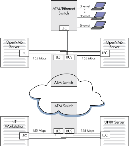
9.5.6.6 LAN Emulation Topology
Figure 9-10 shows
the topology of a typical emulated LAN over ATM.
Figure 9-10 Emulated LAN Topology
9.5.6.7 Classical IP Over an ATM Network
Classical IP (CLIP) implements a data-link level
device that has the same semantics as an Ethernet interface (802.3).
This interface is used by a TCP/IP protocol to transmit 802.3 (IEEE
Ethernet) frames over an ATM network. The model that OpenVMS follows
for exchanging IP datagrams over ATM is based on RFC 1577 (Classical
IP over ATM).
For information on using LANCP commands to manage
Classical IP, see the HP OpenVMS System Management Utilities
Reference Manual.
9.5.6.8 Specifying the User to Network Interface (UNI)
The ATM software is set to autosense the UNI version
by default. Setting bit 3 of the system parameter, LAN_FLAGS, to 1
enables UNI 3.0 over all ATM adapters. Setting bit 4 of the system
parameter, LAN_FLAGS, to 1 enables UNI 3.1 over all ATM adapters.
9.5.6.9 Enabling SONET/SDH
The ATM drivers have the capability of operating
with either synchronous optical network (SONET) or Synchronous Digital
Hierarchy (SDH) framing. Setting bit 0 of the system parameter, LAN_FLAGS,
to 1 enables SDH framing. Setting bit 0 of the system parameter, LAN_FLAGS,
to 0 enables SONET framing (default). For this to take affect, the
system parameter must be specified correctly before the ATM adapter
driver is loaded.
9.5.6.10 Booting
OpenVMS Alpha does not support ATM adapters as
boot devices.
9.5.6.11 Configuring an Emulated LAN (ELAN)
The LANCP utility sets up an Emulated LAN (ELAN).
If the ELAN is defined in the permanent database, these settings take
effect at boot time. To define the commands in the permanent database
for specific adapters, you invoke the DEFINE DEVICE commands. Once
these commands define the adapters in the permanent database, the
ELAN can be started during system startup.
You can also invoke the LANCP SET commands to
start up an ELAN after the system is booted.
The following example shows the DEFINE DEVICE
commands that define the adapter in the permanent database:
$ mcr lancp
LANCP> define device ela0/elan=create
LANCP> define device ela0/elan=(parent=hwa0,type=csmacd,size=1516)
LANCP> define device ela0/elan=(descr="An ATM ELAN")
LANCP> define device ela0/elan=enable=startup
LANCP> list dev ela0/param

Device Characteristics, Permanent Database, for ELA0:
                  Value  Characteristic
                  ——  —————
                   HWA0  Parent ATM device
          "An ATM ELAN"  Emulated LAN description
                   1516  Emulated LAN packet size
                CSMA/CD  Emulated LAN type
                    Yes  Emulated LAN enabled for startup
LANCP> exit
$
The following example shows the SET DEVICE commands
required for setting up an ELAN with the desired parameters. Note
that some of the commands generate a console message.
$ mcr lancp
LANCP> set dev ela0/elan=create

%%%%%%%%%%%  OPCOM  26-MAR-2001 16:57:12.89  %%%%%%%%%%%
Message from user SYSTEM on ALPHA1
LANACP LAN Services
Found LAN device ELA0, hardware address 00-00-00-00-00-00

LANCP> set dev ela0/elan=(parent=hwa0,type=csmacd,size=1516)
LANCP> set dev ela0/elan=(descr="An ATM ELAN")
LANCP> set dev ela0/elan=enable=startup

%ELDRIVER, LAN Emulation event at 26-MAR-1996 16:57:28.78
%ELDRIVER, LAN Emulation startup: Emulated LAN 1 on device ELA0

LANCP> sho dev ela/char

   Device Characteristics ELA0:
                  Value  Characteristic
                  ——  —————
                 Normal  Controller mode
               External  Internal loopback mode
                CSMA/CD  Communication medium
                     16  Minimum receive buffers
                     32  Maximum receive buffers
                     No  Full duplex enable
                     No  Full duplex operational
            Unspecified  Line media
                     10  Line speed (megabits/second)
                CSMA/CD  Communication medium
                 "HWA0"  Parent ATM Device
          "An ATM ELAN"  Emulated LAN Description
   3999990000000008002B  LAN Emulation Server ATM Address
   A57E80AA000302FF1300
                Enabled  Emulated LAN State
LANCP> exit
$
For information about using LANCP and system manager
commands with qualifiers for LAN emulation over ATM networks, see
the HP OpenVMS System Management Utilities Reference Manual and HP OpenVMS System Manager's Manual.