To illustrate the various levels of data availability
obtainable through Volume Shadowing for OpenVMS, this section provides
a representative sample of hardware configurations. Figure 2-2 through Figure 2-4 show possible
system configurations for shadow sets. The hardware used to describe
the sample systems, while intended to be representative, is hypothetical;
they must be used only for general observations about availability
and not as a suggestion for any specific configurations or products.
In all the following examples, the shadow set
members use the $allocation-class$ddcu: naming convention. The shadow set (also known
as the virtual unit) is represented by DSAn:, where n represents a number between
0 and 9999. These naming conventions are described in more detail
in “Creating a Shadow Set ”.
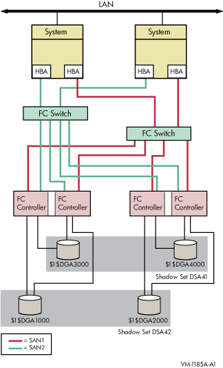
Figure 2-2 shows an OpenVMS Cluster system consisting of two systems connected
to the same two shadow sets. Each system has two host-based
adapters (HBAs) connecting it to the same two Fibre Channel (FC) switches.
In turn, the FC switches are connected to two dual controllers, which
are connected to two shadow sets.
Each shadow set member is connected by two paths,
one to each of the dual controllers of one storage system. Each shadow
set member can fail over between controllers independently of each
other. Each system can access both shadow sets by direct connections.
This configuration provides coverage against:
Failure of one HBA per system
Failure of one or more controllers
Failure of one disk per shadow set
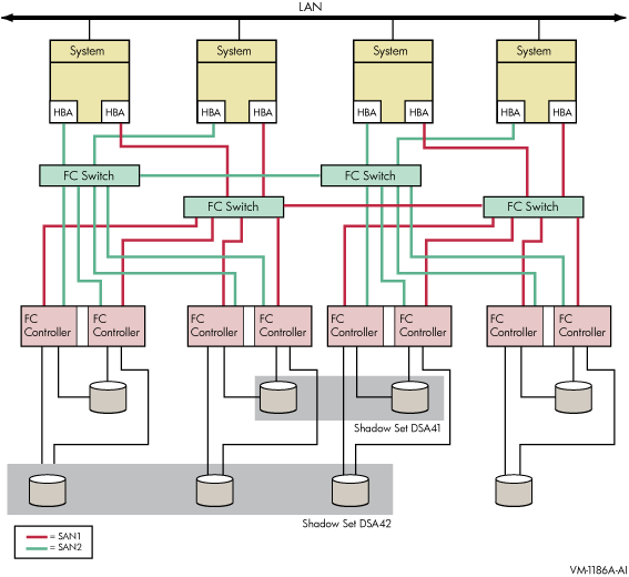
Figure 2-3 shows an OpenVMS Cluster system consisting of four systems. Each
system in the cluster is identical to each system shown in Figure 2-2. In addition
to the protection offered by Figure 2-2, this OpenVMS Cluster configuration provides
greater protection from:
Component failure because there are twice as many
components
Failure of one or two devices in shadow set DSA42
because it is a three-member set
This type of configuration provides continued
access to data in spite of the failure of any one or more of these
systems or switches.
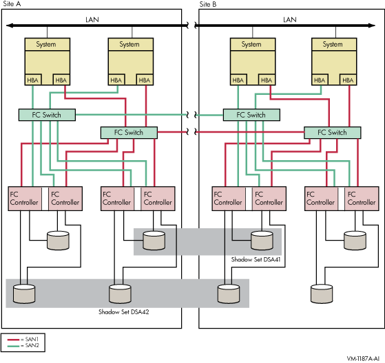
Figure 2-4 shows an OpenVMS Cluster system identical to Figure 2-3 except that the
four systems are not in a single location. Instead, two systems are
at one site and two at a second site. This figure illustrates how
you can shadow data disks over long distances. Members of each shadow
set are configured between two distinct and widely separated locations
— a multiple-site OpenVMS Cluster system. The OpenVMS systems
and shadowed disks in both locations function together as a single
OpenVMS Cluster system and shadow set configuration. If a failure
occurs at either site, the critical data is still available at the
remaining site.