Software > OpenVMS Systems > Documentation > 732final > 6645 HP OpenVMS Systems Documentation |
HP TCP/IP Services for OpenVMS
|
| Previous | Contents | Index |
An anycast address is an identifier for a set of interfaces typically belonging to different nodes. Packets sent to an anycast address are delivered to one of the interfaces identified as the "nearest" address, according to the routing protocol's measure of distance.
Anycast addresses are allocated from the unicast address space, and cannot be distinguished from unicast addresses. Only the subnet-router anycase address and addresses defined in RFC 2526 are easily identified. Packets sent to the subnet-router anycast address are delivered to the router closest to the originating host only. Figure 1-9 shows the format of anycast addresses.
Figure 1-9 Anycast Address

A multicast address is an identifier for a group of nodes. It is similar to an IPv4 multicast address. Figure 1-10 shows the format for multicast addresses.
Figure 1-10 IPv6 Multicast Address
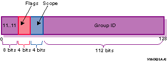
In the multicast address format, the fields have the following definitions:
| 11..11 | Identifies the address as multicast. | ||||||||||||||||||||||||||||||||||
| Flags |
Can be either of the following values:
|
||||||||||||||||||||||||||||||||||
| Scope |
Indicates the scope of the multicast group. The following table lists
the scope values:
|
||||||||||||||||||||||||||||||||||
| Group ID | Identifies the multicast group within the specified scope. |
Table 1-1 lists some well-known multicast addresses.
| Multicast Address | Meaning |
|---|---|
| FF01::1 | All nodes (interface-local) |
| FF02::1 | All nodes (link-local) |
| FF01::2 | All routers (interface-local) |
| FF02::2 | All routers (link-local) |
| FF05::2 | All routers (site-local) |
| FF02::1:FFxx:xxxx | Solicited-node address |
Each IPv6 address has a unique pattern of leading (high-order) bits that indicates its address type. Table 1-2 lists some IPv6 address types and their prefixes.
| Address Type | Binary Prefix | IPv6 Notation |
|---|---|---|
| Unspecified | 00...0 (128 bits) | ::/128 |
| Loopback | 00...1 (128 bits) | ::1/128 |
| Multicast | 11111111 | FF00::/8 |
| Link-local unicast | 1111111010 | FE80::/10 |
| Site-local unicast | 1111111011 | FEC0::/10 |
| Global unicast | (everything else) |
The BIND resolver has been updated as described in the following RFC draft:
draft-ietf-ipngwg-scoping-arch-04.txt |
This change allows the specification of an IPv6 nonglobal address without ambiguity by also specifying an intended scope zone. The format is as follows:
address%zone_id
The format of the nonglobal address includes the following:
For example, the following specifies a nonglobal address on interface WE0:
fe80::1234%WE0 |
The IPv6 address changes have led to the following definitions for configuring addresses:
In the stateless model, nodes learn address prefixes by listening for Router Advertisement packets. Addresses are formed by combining the prefix with a data link-specific interface token, which is typically derived from the data link address of the interface. This model is favored by administrators who do not need tight control over address configuration. See RFC 2462 for more information.
In DHCPv6, hosts may request addresses, configuration information and services from dedicated configuration servers. This model is favored by administrators who want to delegate addresses based on a client/server model.
This version of TCP/IP Services for OpenVMS does not support DHCPv6. |
In both cases, the resulting addresses have associated lifetimes, and systems must be able to acquire new addresses and release expired addresses. Combined with the ability to register updated address information with Domain Name System (DNS) servers, these mechanisms provide a path towards network renumbering and provide network administrators with control over the use of network addresses without manual intervention on each host on the network.
The Domain Name System (DNS) provides support for mapping names to IP addresses and mapping IP addresses back to their corresponding names. Because of the increased size of the IPv6 address, the DNS has the following new features:
b.a.9.8.7.6.5.0.4.0.0.0.3.0.0.0.2.0.0.0.1.0.0.0.0.0.0.0.1.2.3.4.IP6.ARPA |
IPv6 addresses are now being deployed by the regional registries. See the IANA web page at the following location for more information:
http://www.iana.org |
In addition, you can contact your Internet Service Provider (ISP) to obtain an IPv6 address.
Because of the need to test various implementations of the IPv6 RFCs, the IETF has defined a temporary IPv6 address allocation scheme. You can assign the addresses in this scheme to hosts and routers for testing IPv6 on the 6bone (a prototype IPv6 implementation that can be used for testing). See the 6bone home page at the following location for more information about 6bone address allocation and assignment:
http://www.6bone.net |
The planning stage for a multiyear phaseout of the 6bone has begun.
At the present time, the 6bone test addresses are aggregatable global unicast addresses. Contact your 6bone service provider (for example, gw-6bone@pa.dec.com ) for a 6bone address delegation.
Because the Internet and most likely your network are based on IPv4, you need to know how to use this routing infrastructure to carry your IPv6 traffic while you gradually build up your IPv6 routing infrastructure. The best mechanism to employ for routing IPv6 traffic across IPv4 routing infrastructures is tunneling. The following types of tunnels are supported:
The following sections describe each tunnel and its advantages and disadvantages. The more powerful the tunnel, the more configuration and administration it requires.
An IPv6 automatic tunnel is the simplest tunnel to configure and deploy. This mechanism enables hosts with a globally unique IPv4 address to automatically create a tunnel over an IPv4 network. The tunnel is created as a virtual interface (TN0) and is configured with an IPv4-compatible IPv6 address, which is derived from the IPv4 address. The destination address of the packet determines the tunnel destination endpoint. See Section 1.2.2.1 for more information about IPv4-compatible IPv6 addresses.
This mechanism is good for introducing hosts to IPv6 because it permits application porting, testing, and experimentation with the IPv6 protocol. However, an automatic tunnel has the following limitations:
A 6to4 tunnel is a type of automatic tunnel, but it offers greater connectivity. This mechanism enables a special IPv6 site, called a 6to4 site, with a single, globally unique IPv4 address to automatically create a tunnel over an IPv4 network to communicate with other 6to4 sites. The tunnel is created as a virtual interface (TNn) on a node at the IPv4 network attachment point. This node is either an individual host or a router called a border router. The tunnel is configured with a special 6to4 address that is derived from the IPv4 address. The destination address of the packet determines the tunnel destination endpoint.
Within the 6to4 site, the border router creates the 6to4 site prefix from its globally unique IPv4 address and advertises the prefix to all nodes in the 6to4 site. Each node automatically configures its 6to4 address based on the 6to4 prefix; no special configuration is necessary. Nodes within the 6to4 site communicate with each other using native IPv6. Any traffic that is addressed outside the site is forwarded to the border router.
This mechanism is easy to configure and can be deployed in a production environment. However, a 6to4 tunnel has the following limitations:
A configured tunnel is the most complex tunnel to configure and deploy. There are two types of configured tunnels:
A configured tunnel is created as a virtual interface (ITn) and uses IPv4 addresses (IPv4 configured tunnel) or IPv6 addresses (IPv6 configured tunnel) as the source and destination endpoints. If you want to send IPv6 traffic through any configured tunnel, you configure an IPv6 address on the tunnel interface. If you want to send IPv4 traffic through any configured tunnel, you configure an IPv4 address on the tunnel interface.
This mechanism is the most powerful tunneling mechanism, but has the following limitations:
This section shows some example IPv6 configurations. Select a configuration that most closely matches the environment in which you want to configure IPv6 on your system.
Figure 1-11 shows a simple LAN configuration in which host A and host B communicate using IPv6 with no router.
Figure 1-11 Host-to-Host Configuration with No Router
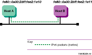
Figure 1-12 shows a simple LAN configuration in which host A, host B, and router A communicate using IPv6. Host A and host B obtain global addresses from router A.
Figure 1-12 Host-to-Host Configuration with Router
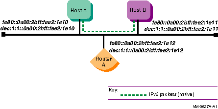
Figure 1-13 shows a configuration in which two IPv6 networks are connected through an IPv6 router (router A).
Figure 1-13 IPv6 Network to IPv6 Network with Router Configuration
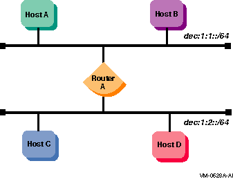
Figure 1-14 shows a configuration in which four IPv6 networks are connected using three routers. The three routers exchange routing information with each other using the RIPng protocol.
Figure 1-14 Multiple IPv6 Networks and Multiple Routers Configuration
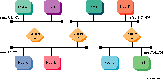
Figure 1-15 shows a configuration in which host A and host B, connected to an IPv4 network, communicate using IPv6 through an IPv4 tunnel.
Figure 1-15 Host-to-Host Configuration over Tunnel
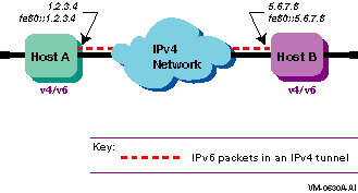
Figure 1-16 shows a configuration in which host X is connected to an IPv4 network. Router A, an IPv6 router, is connected to the same IPv4 network and is also connected to two IPv6 networks. Host X communicates with host B using IPv6 through an IPv4 tunnel between host X and router A.
Figure 1-16 Host-to-Router Configuration over Tunnel
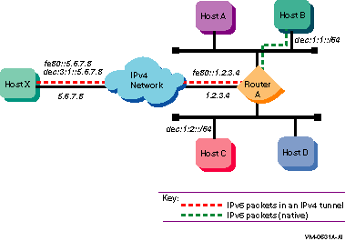
Figure 1-17 shows a configuration in which four IPv6 networks are connected through two routers and an IPv4 network. Host A communicates with host F through an IPv4 tunnel between router A and router B.
Figure 1-17 IPv6 Network-to-IPv6 Network Configuration over Tunnel
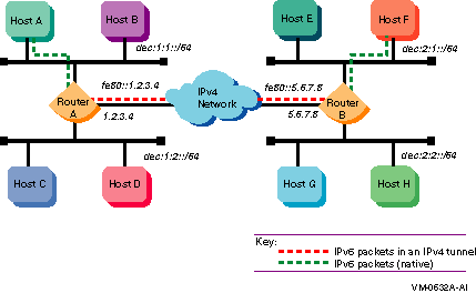
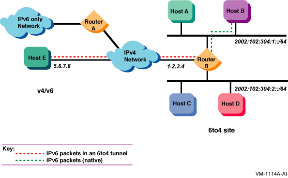
Figure 1-18 shows a configuration in which host E is connected to an IPv4 network. Router B, an IPv6 router, is connected to the same IPv4 network and also is connected to two IPv6 networks. Host E communicates with host B using a 6to4 tunnel between host E and router B.
Figure 1-18 IPv6 Network-to-IPv6 Network Configuration over Tunnel
| Previous | Next | Contents | Index |