Software > OpenVMS Systems > Documentation > 82final > 6466 HP OpenVMS Systems Documentation |
Upgrading Privileged-Code Applications on OpenVMS Alpha and OpenVMS I64 Systems
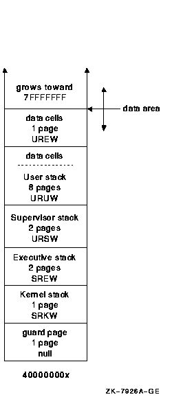
6.2.5 Per-Kernel Thread Data CellsSeveral pages in P1 space contain process state in the form of data cells. A number of these cells must have a per-kernel thread equivalent. These data cells do not all reside on pages with the same protection. Because of this, the per-kernel area reserves approximately two pages for these cells. Each page has a different page protection; one page protection is user read, user write (URUW), the other is user read, executive write (UREW). The top of the user stack is used for the URUW data cells. 6.2.6 Layout of the Per-Kernel ThreadEach per-kernel thread area contains a set of stacks and two pages for data. Each area is a fixed size. For a system using the default values for the kernel stack and user stack size, each area has the layout shown in Figure 6-1. Figure 6-1 Default Kernel Stack and User Stack Sizes 
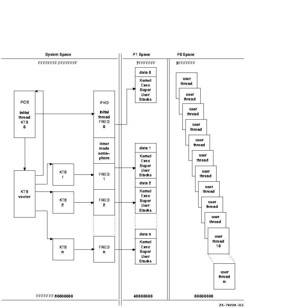
6.2.7 Summary of Process Data StructuresProcess creation results in a PCB/KTB, a PHD/FRED, and a set of stacks. All processes have a single kernel thread, the initial thread. A multithreaded process always begins as a single threaded process. A multithreaded process contains a PCB/KTB pair and a PHD/FRED pair for the initial thread; for its other threads, it contains additional KTBs, additional FREDs, and additional sets of stacks. When the multithreaded application exists, the process returns to its single threaded state, and all additional KTBs, FREDs, and stacks are deleted. Figure 6-2 shows the relationships and locations of the data structures for a process. Figure 6-2 Structure of a Multithreaded Process 
6.3 Process Identifiers (PIDs)OpenVMS qualifies much context by the process ID (PID). With the implementation of kernel threads, much of that process context moves to the thread level. With kernel threads, the basic unit of scheduling is no longer the process but rather the kernel thread. Because of this, kernel threads need a method to identify them which is similar to the PID. To satisfy this need, the meaning of the PID is extended. The PID continues to identify a process, but can also identify a kernel thread within that process. An overview follows that presents the features of the PID, and the extended process ID (EPID), which is the cluster-visible extension of the PID. The PID in this form is typically known as the internal PID (IPID). It consists of two pieces of information, both one word in length. Figure 6-3 shows the layout. Figure 6-3 Process ID (PID) 
The low word is the process index (PIX). The PIX is used as an index into the PCB vector. This is a vector of PCB addresses. Therefore the PIX gives a quick method of determining the PCB address given a PID. Another array, also indexed by PIX, contains a sequence number entry for each PIX. The sequence number increments every time a PIX is reused. The high word of the IPID is a copy of the value in the array for a particular PIX. This feature validates a PID to ensure that the ID is not for a process which has been deleted. The sequence number in the IPID must match the one in the sequence number array for that PIX. The EPID is the cluster-visible PID. It consists of five parts, as Figure 6-4 shows. Figure 6-4 Extended Process ID (EPID) 
The EPID takes its low 21 bits from the two word IPID fields seen in Figure 6-3. The value of MAXPROCESSCNT determines the number of bits within the 21 bits used for the PIX (5 to 13 bits). The sequence number uses the remaining bits (8 to 16 bits). The PIX cannot be larger than 8192; the sequence number no larger than 32767. If the system is an OpenVMS cluster member, the next 10 bits of the EPID uniquely identify the PID within the cluster. They contain 8 bits of the cluster system ID (CSID) for the system, and a 2 bit sequence number. The system service SYS$GETJPI uses the high bit (31). If set, the bit specifies that the PID is a wildcard context value. This allows collecting information for all processes in the system. 6.3.1 Multithread Effects on the PIDWith kernel threads implementation, the PID's definition undergoes two changes:
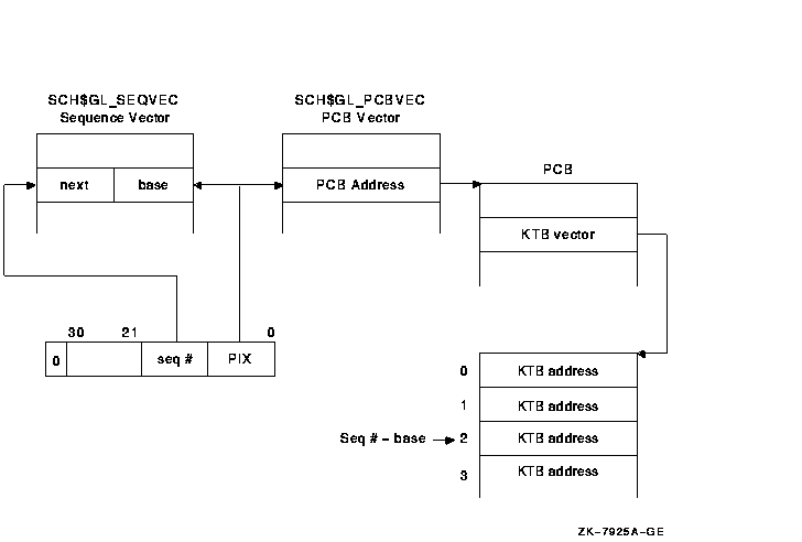
6.3.2 Range Checking and Sequence VectorsEvery process has at least one kernel thread, the initial thread, which is always thread ID zero; therefore, given a particular PID, the PIX continues to be used as an index into the PCB and sequence vectors. A range check validates the sequence numbers. Before kernel threads implementation, the sequence number vector (SCH$GL_SEQVEC) was a vector of words. After kernel threads implementation, it is a vector of longwords that enables range checking for sequence number validation. The low word in each longword is the base sequence number for a particular PIX, and the upper word is the next sequence number for that PIX. The sequence number for a single-threaded process must be equal to the base value. Kernel threads PID sequence numbers must fall within the base and next values. Figure 6-5 shows the flow of range checking of sequence numbers. Figure 6-5 Range Checking and Sequence Vectors 
6.4 Process Status BitsSimilar to the fields in the PCB that migrate to the KTB, there are several status bits that need to be per thread. The interface for the SYS$GETJPI and SYS$PROCESS_SCAN system services indicates that the entire longword fields that contain the status bits can be returned. Therefore, all the status bits must remain defined as they are. The PCB specific bits are "reserved" in the KTB structure definition. Likewise, the KTB specific bits are "reserved" in the PCB. Because the PCB is really an overlaid structure with the initial thread's KTB, just the PCB status bits need to be returned for the initial thread. The status longword returned for other threads is built by first masking out the initial thread's bits, and then OR'ing the remainder with the status longword in the appropriate KTB. If a thread in a multithreaded process requests information about itself using SYS$GETJPI (passes PID=0), then the status bits for the kernel thread it is running on are returned. Since each kernel thread has its own PID, SYS$GETJPI can be called for each of the kernel threads in a process. The return status bits are the combination of the PCB status bits and those in the KTB associated with the input PID.
|