 |
HP OpenVMS System Management Utilities Reference
Manual
H.4.2.16 STATES Class Record
The STATES class record contains data describing the number of
processes in each of the scheduler states. The STATES class record has
a record type of 1 and a size of 72 bytes.
Figure H-23 illustrates the format of the STATES class record.
Figure H-23 STATES Class Record Format
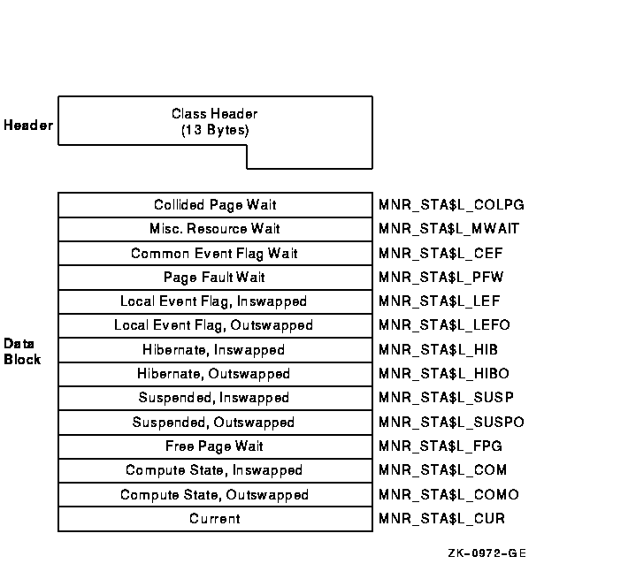
The following table describes the fields in the data block for the
STATES class record:
| Field |
Symbolic Offset |
Contents |
Collided
Page Wait
|
MNR_STA$L_COLPG
|
Number of processes in collided page wait (longword,L)
|
Misc
Resource Wait
|
MNR_STA$L_MWAIT
|
Number of processes in miscellaneous resource wait (longword,L)
|
Common Event
Flag Wait
|
MNR_STA$L_CEF
|
Number of processes in common event flag wait (longword,L)
|
Page Fault
Wait
|
MNR_STA$L_PFW
|
Number of processes in page fault wait (longword,L)
|
Local Event Flag,
Inswapped
|
MNR_STA$L_LEF
|
Number of processes in local event flag wait, inswapped (longword,L)
|
Local Event Flag,
Outswapped
|
MNR_STA$L_LEFO
|
Number of processes in local event flag wait, outswapped (longword,L)
|
Hibernate,
Inswapped
|
MNR_STA$L_HIB
|
Number of processes in hibernate wait, inswapped (longword,L)
|
Hibernate,
Outswapped
|
MNR_STA$L_HIBO
|
Number of processes in hibernate wait, outswapped (longword,L)
|
Suspended,
Inswapped
|
MNR_STA$L_SUSP
|
Number of processes in suspended wait, inswapped (longword,L)
|
Suspended,
Outswapped
|
MNR_STA$L_SUSPO
|
Number of processes in suspended wait, outswapped (longword,L)
|
Free Page
Wait
|
MNR_STA$L_FPG
|
Number of processes in free wait (longword,L)
|
Compute State,
Inswapped
|
MNR_STA$L_COM
|
Number of processes in compute state, inswapped (longword,L)
|
Compute State,
Outswapped
|
MNR_STA$L_COMO
|
Number of processes in compute state, outswapped (longword,L)
|
|
Current
|
MNR_STA$L_CUR
|
Number of current processes (longword,L)
|
H.4.2.17 SYSTEM Class Record
The SYSTEM class record contains data describing the overall operation
of the three major system components (CPU, memory, I/O). The SYSTEM
class record has a record type of 17 and a size of 52 bytes. Note that
when the SYSTEM class is recorded, the PROCESSES, STATES, and MODES
classes are also recorded, even if not explicitly requested.
Figure H-24 illustrates the format of the SYSTEM class record.
Figure H-24 SYSTEM Class Record Format
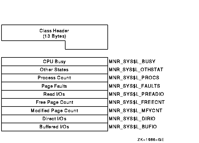
The following table describes the fields in the data block for the
SYSTEM class record:
| Field |
Symbolic Offset |
Contents |
|
CPU Busy
|
MNR_SYS$L_BUSY
|
Count of clock ticks (10-millisecond units) spent in all CPU modes
since system was booted (longword,C)
|
|
Other States
|
MNR_SYS$L_OTHSTAT
|
Number of processes in states other than LEF, LEFO, HIB, HIBO, COM,
COMO, PFW, and MWAIT (longword,L)
|
|
Process Count
|
MNR_SYS$L_PROCS
|
Number of processes in system (longword,L)
|
|
Page Faults
|
MNR_SYS$L_FAULTS
|
Count of page faults for all working sets (longword,C)
|
|
Read I/Os
|
MNR_SYS$L_PREADIO
|
Count of read I/Os resulting from disk page faults (longword,C)
|
|
Free Page Count
|
MNR_SYS$L_FREECNT
|
Number of pages currently on free-page list (longword,L)
|
|
Modified Page Count
|
MNR_SYS$L_MFYCNT
|
Number of pages currently on modified-page list (longword,L)
|
|
Direct I/Os
|
MNR_SYS$L_DIRIO
|
Count of direct I/O operations (longword,C)
|
|
Buffered I/Os
|
MNR_SYS$L_BUFIO
|
Count of buffered I/O operations (longword,C)
|
H.4.2.18 TIMER Class Record
The TIMER class record contains data that is useful to the OpenVMS
executive when monitoring timer queue entries (TQEs). The TIMER class
record has a record type of 26 and a size of 32 bytes.
Figure H-25 illustrates the format of the TIMER class record.
Figure H-25 TIMER Class Record Format
The following table describes the contents of each of the TIMER class
record fields:
| Field |
Symbolic Offset |
Contents |
|
Total TQEs
|
MNR_TMR$L_TQE_TOTAL
|
Count of all TQEs processed per second.
|
|
SYSUB TQEs
|
MNR_TMR$L_TQE_SYSUB
|
Count of SYSUB TQEs processed per second.
|
|
Timer TQEs
|
MNR_TMR$L_TQE_TIMER
|
Count of timer requests made by users per second.
|
|
Wakeup TQEs
|
MNR_TMR$L_TQE_WAKEUP
|
Count of wakeup timer requests made by users per second.
|
H.4.2.19 TRANSACTION Class Record
The TRANSACTION class record contains data describing the operations of
the DECdtm transaction manager. The TRANSACTION class has a record type
of 22 and a size of 72 bytes. Figure H-26 illustrates the format of
the TRANSACTION class record.
Figure H-26 TRANSACTION Class Record Format
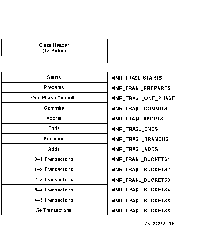
The following table describes the contents of each of the TRANSACTION
class record fields:
| Field |
Symbolic Offset |
Contents |
|
Starts
|
MNR_TRA$L_STARTS
|
Count of transactions started. The number of times that calls on the
local node to $START_TRANS have completed successfully (longword, C).
|
|
Prepares
|
MNR_TRA$L_PREPARES
|
Count of transactions that have been prepared (longword, C).
|
|
One Phase Commits
|
MNR_TRA$L_ONE_PHASE
|
Count of one-phase commit events initiated (longword, C).
|
|
Commits
|
MNR_TRA$L_COMMITS
|
Count of transactions committed. This is the combined total of
one-phase and two-phase commits (longword, C).
|
|
Aborts
|
MNR_TRA$L_ABORTS
|
Count of transactions aborted. Combined total of planned and unplanned
aborts (longword, C).
|
|
Ends
|
MNR_TRA$L_ENDS
|
Count of transactions ended. The number of times that calls on the
local node to $END_TRANS have completed successfully (longword, C).
|
|
Branches
|
MNR_TRA$L_BRANCHS
|
Count of transaction branches started on the local node (longword, C).
|
|
Adds
|
MNR_TRA$L_ADDS
|
Count of transaction branches added on the local node (longword, C).
|
|
0-1 Transactions
|
MNR_TRA$L_BUCKETS1
|
Count of transactions with a duration of less than 1 second (longword,
C).
|
|
1-2 Transactions
|
MNR_TRA$L_BUCKETS2
|
Count of transactions with a duration of 1 to 2 (1.99) seconds
(longword, C).
|
|
2-3 Transactions
|
MNR_TRA$L_BUCKETS3
|
Count of transactions with a duration of 2 to 3 seconds (longword, C).
|
|
3-4 Transactions
|
MNR_TRA$L_BUCKETS4
|
Count of transactions with a duration of 3 to 4 seconds (longword, C).
|
|
4-5 Transactions
|
MNR_TRA$L_BUCKETS5
|
Count of transactions with a duration of 4 to 5 seconds (longword, C).
|
|
5+ Transactions
|
MNR_TRA$L_BUCKETS6
|
Count of transactions with a duration greater than 5 seconds (longword,
C).
|
Appendix I
HP OpenVMS Integrity servers Serial Multiplexer (MUX) Support for Integrity Servers
RS232 serial lines and multiplexers are used for a variety of tasks,
from traditional terminal connections to low-speed system-to-system
communication and even for communication with remote instruments.
OpenVMS has traditionally supported adding serial lines at the same
time as option-card-based multiplexers. This solution requires
dedicating I/O slots; it also limits the choices of option cards
available.
With the widespread adoption of the Universal Serial Bus (USB) on
industry-standard platforms, a variety of USB-based serial-line dongles
and multiplexers are now available. (Dongles are single-function
devices with a connector.) OpenVMS has moved away from
option-card-based serial multiplexers and has adopted USB to add serial
lines to HP Integrity servers.
USB-based serial devices have many configurations; these vary from
single-line dongles to rack-mounted 16-line (or more) multiplexers.
Rather than using one or two option-card solutions with 8 or 16 lines
for all configurations, you can now configure USB to meet your exact
requirements.
Testing shows that the USB-based serial multiplexers perform as well as
(or better than) their option-card counterparts and cause very low
overhead to the system. In fact, the overhead is lower than
option-card-based multiplexers.
OpenVMS has developed USB interface drivers for the three most popular
RS232 chipsets on the market:
- Prolific PL2303
- FTDI FT232AM and FTDI FT232BM
- Inside Out Networks EDGEPORT (from DIGI)
Many sources exist for products based on these chips. OpenVMS has
purchased a number of representative products on the open market to
validate them. A list of devices that OpenVMS has tested, along with an
overview of their capabilities and limitations, is in the section
called "Tested Devices." (OpenVMS intends to continue to
update this list regularly and to make it available on its Web page.)
Because consumer products are often short-lived, OpenVMS periodically
samples the market for new devices. You can also contact the OpenVMS
organization directly at the following Web site to request that a
specific product be validated:
http://h20219.www2.hp.com/services/cache/77481-0-0-225-121.html
|
For the devices listed in "Tested Devices," the OpenVMS
organization accepts bug reports from customers and produces driver ECO
fixes as needed. Driver support for these devices ships with the base
operating system and does not require a separate layered-product kit or
license.
Tested Devices
The following devices have been tested on OpenVMS:
- Inside Out Networks EDGEPORT/416 (DB9) and EDGEPORT/8
(DB25)
- The EDGEPORT/416 DB9 (DIGI Part Number 301-1000-10) is a dual RS232
controller with 8 lines per controller (and a total of 16 lines). The
device is packaged as two 8-line controllers behind a USB hub; it also
provides 4 additional USB expansion ports. The device is powered from a
DC adapter integrated on the back of the device.
- The EDGEPORT/8 DB25 (DIGI Part Number 301-1016-08) is a single
RS232 controller with a total of 8 lines. The device is bus powered and
does not require an external power supply.
These devices are rack mountable. Both devices have a unique serial
number; they are always assigned the same name, regardless of the USB
port into which they are plugged. Testing of these devices shows
reliable operation in both software flow control and raw binary (no
flow control) modes at up to 115,200 baud.
The system parameter
TTY_SILOTIME controls latency; it trades throughput and system overhead
for latency. The default value for TTY_SILOTIME is 8. This value is
multiplied by 100 and is used to represent the number of times a query
is sent to the device for more data after a character transmit or
receive.
If no input (or no subsequent output) is seen after 800
responses to the query, the driver stops sending queries to the device
and waits for an input interrupt. Reducing the TTY_SILOTIME value
allows the device to buffer more data, with slightly higher latency.
Increasing the value of TTY_SILOTIME makes the device more
sensitive to latency but decreases buffering and overall throughput; it
also adds more system and USB overhead. Setting TTY_SILOTIME to zero
causes the driver to send input queries to the device continually. This
setting causes the lowest latency, the highest system overhead, and the
lowest throughput possible.
Note
The TTY_SILOTIME system parameter has no effect on Prolific or FTDI
devices. The EDGEPORT controller design is different from devices that
do not respond to a request until the device has data and a buffer
timeout is reached. As a result, input data is buffered whenever
possible.
In contrast, the EDGEPORT, responds immediately to input
requests regardless of the amount of data available, and sends
asynchronous reports about the availability of new data. This allows
either a highly buffered implementation or one that is similar to
polling.
|
- Cool Gear (VScom) FTDI 8-Port RS232 (DB9)
This
device (USBGEAR.COM Order Number 8XDB9-USB) is an 8-port DC
adapter-powered device that contains 8 individual FDTI FT232BM chips
and configures as 8 individual single-line controllers.
The
controllers have unique serial numbers and are always assigned the same
OpenVMS name, regardless of the USB port into which a controller is
plugged.
Tests of this device show reliable operation in both
software flow control and raw binary (no flow control) modes at up to
115,200 baud.
- Prolific PL2303 4-Port RS232 Cable Dongle (DB9)
This device (USBGEAR.COM Order Number USBG-4X232) is a 4-port wire
dongle (4 wires connected to a single USB connector), with 4xDB9
connectors on the wires. The cables contain a USB hub and 4 PL2303
serial controllers. The device is bus powered and does not need a
separate power supply.
This device provides no serial number. The
persistence of its name is based on where it is plugged (that is, its
path topology); when the device is plugged at a different location, it
appears to be a different instance of the device.
Tests of this
device show reliable operation in both software flow control and raw
binary (no flow control) modes at up to 115,200 baud.
- FTDI 232AM Single-Port RS232 Dongle (DB9)
This
device (USBGEAR.COM Order Number USBG-232MINI) is a single-port dongle
(no wire) that plugs into a single USB port. The device is bus powered
and needs no external power supply.
The device provides a serial
number and is configured with the same OpenVMS device name regardless
of where it is plugged.
Tests of the device show reliable operation
in both software flow control and raw binary (no flow control) modes at
up to 115,200 baud.
- USBG-4-DOC-1 Multifunction Docking Station
This multifunction device (USBGEAR.COM Order Number USBG-4-DOC
includes the following:
- 1 Prolific RS232 (DB9) serial port
- A PS2-USB keyboard port converter
- A PS2-USB mouse port converter
- A bidirectional parallel port
- A 4-port USB hub
This device is useful when only a single line is needed and when a
parallel port, PS2 keyboard or mouse connectivity, or additional USB
ports are required.
The device provides no serial number, and its
name persistence is based on where it is plugged (path topology). When
the device is plugged in at a different location, it appears to be a
different instance of the device.
Tests of this device show
reliable operation in both software flow control and in raw binary (no
flow control) modes at up to 115,200 baud.
I.2 Device Installation
The low-range and mid-range Integrity servers provide builtin USB
controllers and at least two ports on the system. High-end cell-based
systems often do not have builtin USB controllers and sometimes require
an optional card (HP Part Number A6869A) to add USB ports.
If no keyboard and mouse are used on the system, you can connect the
USB serial device directly to one of the USB ports on the system. The
USB design allows expansion of available ports using a hierarchical
series of hubs. A hub usually expands an available USB port into 4 USB
ports; this means that two ports on most systems can be expanded up to
as many as 128 ports by using additional hub devices. By default,
OpenVMS recognizes USB devices and configures them automatically (with
no additional user action).
UCM assigns USB device names as devices are discovered. When you use
multiple similar devices, the order of discovery determines the name.
The permanent (persistent name) database obtains the same OpenVMS
device name each time the system is booted and the device is found.
Devices that have a unique serial number are always given the same name
after they are added to the permanent database. Devices with no serial
number are given the same name only when they are plugged into the USB
bus hierarchy in the same place as when the name was made persistent.
If the device is moved to a different USB port, UCM considers it a new
device, and it is given its own unique name.
For more information about controlling USB device configuration, see
the HP OpenVMS System Management Utilities Reference Manual.
The following actions are required to configure a serial multiplexer:
- Boot the system and then connect the device. (You can connect the
device prior to booting as well.)
- By default, OpenVMS automatically detects and connects the device.
You can verify this by entering the following command:
The lines are ready to use and are always given the same name or names
when OpenVMS VMS boots or when the device is connected. (A device
without a serial number, however, is considered to be a different
device when it is connected to a different port.)
|