The OpenVMS LAN software employs a class/port
driver architecture to allow LAN applications to communicate with
other nodes over the LAN device and the network.
The class driver is implemented by a collection
of execlets known as the LAN common routines. The LAN common routines
implement two APIs, QIO and VCI. LAN applications interface to the
LAN device port drivers using these APIs in a common manner across
each type of LAN (Ethernet, FDDI, Token Ring, ATM, and Shared Memory).
An execlet for each LAN medium minimizes the differences between
them so applications can operate transparently over different types
of LANs. LAN over ATM emulates Ethernet and uses the Ethernet LAN
common routines. ATM needs a significant amount of additional support
code to provide LAN emulation (LANE) and Classical IP (CLIP) support.
This support code is located in an ATM execlet. LAN over Shared
Memory also emulates Ethernet and uses the Ethernet LAN common routines.
No additional support code is needed for Shared Memory.
The port drivers operate the LAN hardware, and
there is one port driver for each type of LAN device. Many of the
port drivers operate multiple variations of similar hardware. One
port driver for ATM emulates Ethernet and another emulates IP (called
Classical IP). The port driver for Shared Memory emulates Ethernet.
Unlike the port drivers that directly control LAN hardware, the emulated
port drivers are pseudo drivers that implement a pseudo hardware interface
in software.
When correlated to the OSI Model, the LAN implementation
occupies the bottom two layers, the LAN common routines and LAN port
drivers constitute the Data Link Layer, and the LAN device hardware
the Physical Layer and parts of the Data Link Layer. The LAN drivers
are often called the data link drivers.
9.4.1 LAN Data Structures
The OpenVMS I/O subsystem describes devices in
terms of a Unit Control Block (UCB). There is a UCB for each device,
which may be an actual physical device or a pseudo or virtual device.
LAN devices include physical devices, NICs located in PCI buses,
for example; and virtual devices, a shared memory emulated Ethernet
device, an ATM emulated LAN device, a LAN Failover device, or a VLAN
device. The LAN drivers define an extension to the standard VMS UCB
that includes additional fields needed to provide LAN context.
When a LAN application wants to use a LAN device,
it assigns a channel (opens a port) to the UCB associated with the
LAN device. When this occurs, the VMS I/O subsystem makes a copy
of the device UCB and associates the channel with this cloned UCB.
Then the application can activate the channel by specifying the desired
characteristics of the channel, such as protocol type and what multicast
addresses to enable. The unit 0 UCB is called the template UCB. Each
non-zero UCB represents a channel to the device and contains application-specific
channel characteristics.
Each LAN driver also maintains another structure,
the LAN Station Block (LSB), which contains LAN common information
as well as device-specific data. For each LAN device there is one
LSB and a corresponding unit 0 UCB. The LSB contains device-specific
data the would be inappropriate to include in the UCB structures such
as device rings and device counters.
In summary, the UCBs contain application-specific
data. The LSBs contain device and driver-specific data. There is
one LSB and one template UCB per LAN device that are created and initialized
during device discovery. Whenever an application opens a channel
to a particular LAN device, the template UCB is cloned to a newly
created cloned UCB which represents the channel. There is one cloned
UCB for each channel. When the channel is deassigned, the cloned
UCB ceases to exist along with any context associated with the channel.
Additional data structures are defined to allow
applications to send and receive I/O requests to the LAN drivers,
as described in the following QIO and VCI sections.
9.4.2 Hardware Configuration
When the system boots, system support code probes
the I/O buses looking for I/O devices. On Alpha and Integrity server
systems, device configuration is done by comparing device IDs found
during bus probing with entries in the file SYS$SYSTEM:SYS$CONFIG.DAT.
This file includes the set of supported LAN devices on Alpha and
Integrity server systems, as well as entries for other I/O devices
supported such as SCSI, FibreChannel, USB, ATA and others.
9.4.3 Software Modules
OpenVMS LAN software consists of LAN common routines,
LAN port drivers, LAN Control Programs, and LAN diagnostic software
listed in Table 9-3.
Table 9-3 LAN Software Module
Location
Module
Architecure
Function
SYS$LOADABLE_IMAGES
SYS$LAN.EXE
Alpha, Integrity servers
LAN common routines, common across
all media types
SYS$LOADABLE_IMAGES
SYS$LAN_CSMACD.EXE
Alpha, Integrity servers
LAN common routines, Ethernet-specific
support
SYS$LOADABLE_IMAGES
SYS$LAN_FDDI.EXE
Alpha
LAN common routines, FDDI-specific support
SYS$LOADABLE_IMAGES
SYS$LAN_TR.EXE
Alpha
LAN common routines, Token ring-specific support
SYS$LOADABLE_IMAGES
SYS$LAN_ATM.EXE
Alpha
LAN common routines, ATM-specific support
SYS$LOADABLE_IMAGES
NET$CSMACD.EXE
Alpha, Integrity servers
DECnet-Plus network management
support routines for Ethernet
SYS$LOADABLE_IMAGES
NET$FDDI.EXE
Alpha
DECnet-Plus network management support routines for
FDDI
SYS$SYSTEM
SYS$CONFIG.DAT
Alpha, Integrity servers
Device ID entries for file-based
device configuration
SYS$SYSTEM
LANCP.EXE
Alpha, Integrity servers
LAN Control Program
SYS$SYSTEM
LANACP.EXE
Alpha, Integrity servers
LAN Auxiliary Control Program,
including MOP server
SYS$LIBRARY
SDA$SHARE.EXE
Alpha, Integrity servers
System Dump Analyzer or System
Analyzer
SYS$LIBRARY
LAN$SDA.EXE
Alpha, Integrity servers
SDA extension for LAN drivers
SYS$LOADABLE_IMAGES
LAN port drivers
Alpha, Integrity servers
LAN port drivers
The NET$ modules are only loaded when DECnet-Plus
is configured on the system. SYS$CONFIG.DAT includes LAN devices
as well as any other I/O devices. LAN support represents only a small
portion of the SDA.EXE and SDA$SHARE.EXE images.
On Alpha and Integrity servers, these routines
are separate execlets.
9.4.4 Application APIs
The LAN common routines provide two APIs to allow
applications to interface to the LAN drivers and ultimately to send
and receive data over the network. The APIs allow an application
to initialize a port (assign a channel), send a packet over the port,
receive a packet from the port, and do other management functions
such as set port characteristics, obtain port characteristics and
counters, and to shut down the port (deassign the channel).
The APIs are:
QIO — An unprivileged
interface to the LAN drivers, designed for user mode code.
VCI — A privileged
interface to the LAN drivers that runs in kernel mode at IPL 8, designed
to be very efficient.
9.4.4.1 QIO API
The QIO API is implemented in the LAN common routines
to interface between an application and the LAN port driver in user
mode. The QIO subsystem passes I/O requests from the application
to the LAN driver. The LAN driver performs the requested I/O and
returns status and data to the application.
An application calls SYS$QIO with a function code,
function modifiers, and addresses of buffers that provide any information
needed, such as a buffer containing transmit data, transmit header
data, a buffer to contain receive data and receive header data, and
buffers for setmode and sensemode functions. This information is
passed to the LAN driver via the P1-P6 QIO parameters.
The LAN common routines translate the I/O function
in the QIO request to a transmit, receive, sensemode, setmode, or
diagnose operation and passes the request on to the LAN port driver.
The LAN port driver does the transmit request,
retrieves the receive packet, collects sensemode data, sets characteristics,
or does the diagnose function, and passes the results back through
the LAN common routines, back through the QIO subsystem, and back
to the application.
QIO operations do buffered I/O. This, in addition
to considerable validation of the QIO request, makes for a robust
user mode interface, but less efficient from a performance standpoint
than the VCI interface.
9.4.4.1.1 QIO Program Operation
The following sequence shows a typical application
sequence, to start a port, do transmits and receives, then shut down
a port:
Use the Assign I/O Channel
($ASSIGN) system service to assign I/O channels to one or more of
the LAN device names and devices specified in Title not available through Table 9-3. $ASSIGN creates a new unit control block
(UCB), to which the channel for the port is assigned.
Start the port with the
set mode function and startup function modifier (see “Set Controller Mode”. You must
supply the required P2 buffer parameters listed in Table 9-33.
Perform read, write, and
sense mode operations as needed.
Shut down the port with
the set mode function and shutdown function modifier (see “Shutdown Controller”.
Use the Deassign I/O Channel
($DASSGN) system service to deassign the I/O channel.
The VCI API is implemented in the LAN common routines
to interface between the application and the LAN port driver in kernel
mode at IPL 8. The VCI application calls VCI routines in kernel mode
at IPL 8. The VCI routines are part of the LAN common routines.
There are routines to initiate a port management request (to start,
stop, and change a port) and to initiate a transmit request. The
VCI application provides routines that the LAN common routines calls
for transmit, receive, and port management completion.
An applications calls a VCI initiation routine
with an I/O request that contains the transmit buffer or pointers
to the transmit data, or the port management buffer data.
The LAN common routines process the transmit or
port management request and passes the request on to the LAN port
driver.
The LAN port driver does the transmit request,
or sets characteristics, and passes the results back through the LAN
common routines, and back to the VCI application by calling the application's
completion routine. When a receive packet arrives, the LAN common
routines passes the receive buffer to the VCI application by calling
the application's receive completion routine. When the application
has completed processing the receive data, it returns the receive
buffer to the LAN common routines by calling a return receive buffer
routine.
VCI operations do direct I/O, avoiding buffer
copies in most cases. VCI applications are considered trusted applications,
so must abide by the VCI specification to gain that trust and to ensure
system integrity is maintained operating in kernel mode with privileges.
9.4.5 LAN Addressing
Each LAN device is identified by a hardware address
that is intended to uniquely identify the LAN device and local system
as a node on the network. The hardware address is a 48-bit address
known as a MAC address or Ethernet address.
Ethernet addresses are represented by the Ethernet
standard as six pairs of hexadecimal digits (six bytes), separated
by hyphens (for example, AA-01-23-45-67-FF). The bytes are displayed
from left to right in the order in which they are transmitted; bits
within each byte are transmitted from right to left. In this example,
byte AA is transmitted first; byte FF is transmitted last. (See the
description of NMA$C_PCLI_PHA in Table 9-33, “Set Controller Mode”, for the internal representation
of addresses.)
For Token Ring networks, the address is often
given in bit-reversed form, called canonical format, separated by
colons. For example, AA-01-23-45-67-FF in canonical format is 55:80:C4:A2:E6:FF.
Upon application, IEEE assigns a block of addresses
to a producer of LAN nodes. Thus, every manufacturer has a unique
set of addresses to use. Normally, one address out of the assigned
block of physical addresses is permanently associated with each device
(usually in read-only memory). This address is known as the hardware
address or MAC address of the device. Each individual device has a
unique hardware address.
9.4.5.1 Ethernet Address Classifications
An Ethernet address can be a physical address
of a single node or a multicast address, depending on the value of
the low-order bit of the first byte of the address (this bit is transmitted
first). Following are the two types of node addresses:
Physical address—The
unique address of a single node on a LAN. The least significant bit
of the first byte of a physical address is 0. (For example, in physical
address AA-00-03-00-FC-00, byte AA in binary is 1010 1010, and the
value of the low-order bit is 0.) This is also called an individual
address or unicast address.
Multicast address—A
multi-destination address of one or more nodes on a given LAN. The
least significant bit of the first byte of a multicast address is
1. (For example, in the multicast address 0B-22-22-22-22-22, byte
0B in binary is 0000 1011, and the value of the low-order bit is 1.
This is the first bit of the address as transmitted over the wire.)
9.4.5.2 Selecting an Ethernet Physical Address
The OpenVMS interface to the LAN controllers allows
you to set a physical address of the controller. The selection of
the physical address of a LAN controller is different for Ethernet
and FDDI.
For Ethernet, all users of the controller must
agree on this address. The first user of the controller chooses the
physical address; any additional users of the controller must specify
either the same physical address, no physical address, or change the
address (if allowed). When all channels to the controller are shut
down, the next user to start a channel chooses the physical address.
The controller's physical address is always chosen on the first
successful startup when there are no active ports. If the address
is not chosen at this time, the controller's hardware address
is used as the physical address.
For Ethernet, the Can Change Address parameter
allows the physical address to be changed even though there are active
users. If all current users of the controller have set the NMA$C_PCLI_CCA
parameter to NMA$C_STATE_ON, then the physical address can be changed.
For FDDI, each port using a controller may specify
its own unique physical address. Any combination of sharing of physical
addresses is also allowed across the ports of an FDDI controller.
For example, ports A, B, and C may use one unique physical address
and ports D and E may use another unique address.
9.4.5.3 Ethernet Physical and Multicast Address Values
The following shows the multicast addresses assigned
for use in cross-company communications:.
Value
Meaning
FF-FF-FF-FF-FF-FF
Broadcast
CF-00-00-00-00-00
Loopback assistance
The following lists the commonly used multicast
addresses.
Value
Meaning
AB-00-00-01-00-00
Dump/load assistance
AB-00-00-02-00-00
Remote console
AB-00-00-03-00-00
Level 1 and Level 2 routers
AB-00-00-04-00-00
All end nodes
09-00-2B-02-00-00
Level 2 routers
AB-00-00-05-00-00
through AB-00-03-FF-FF-FF
Reserved for future use
AB-00-03-00-00-00
LAT
AB-00-04-00-00-00
through AB-00-04-00-FF-FF
For use by HP customers for their own applications
AB-00-04-01-00-00
through AB-00-04-01-FF-FF
Local area VMScluster
AB-00-04-02-00-00
through AB-00-04-FF-FF-FF
Reserved for future use
09-00-2B-01-00-00
Bridge management
09-00-2B-01-00-01
Bridge hello multicast
9.4.5.4 Token Ring
Functional Address Mapping
Except for the global broadcast address (FF-FF-FF-FF-FF-FF),
Token Ring hardware does not support the 802 standard group LAN address
mechanism. Instead, it uses functional addresses. Functional addresses are locally administered group addresses (multicast
addresses). The first two bytes of the address are always 03-00 (canonical
format), and the remaining four bytes contain a bit mask that specifies
which of the 32 possible combination masks is being described.
Because most OpenVMS LAN applications use standard
multicast addresses, a mechanism has been designed to map functional
addresses to globally and locally administered multicast addresses.
This allows applications to use the same multicast addresses that
are used in the other LAN media.
Table 9-4 shows the default mapping used by the OpenVMS Alpha Token Ring
drivers:
Table 9-4 Address Mappings of Token Ring Drivers
Multicast Address
Functional Address
Bit-Reversed
Description
09-00-2B-00-00-04
03-00-00-00-02-00
C0:00:00:00:40:00
ISO 9542 All End-system
Network Entities
09-00-2B-00-00-05
03-00-00-00-01-00
C0:00:00:00:80:00
ISO 9542 All Intermediate
System Network Entities
CF-00-00-00-00-00
03-00-00-08-00-00
C0:00:00:10:00:00
Loopback Assistance
AB-00-00-01-00-00
03-00-02-00-00-00
C0:00:40:00:00:00
MOP Dump/Load
AB-00-00-02-00-00
03-00-04-00-00-00
C0:00:20:00:00:00
MOP Remote Console
AB-00-00-03-00-00
03-00-08-00-00-00
C0:00:10:00:00:00
DNA L1 Routers
09-00-2B-02-00-00
03-00-08-00-00-00
C0:00:10:00:00:00
DNA L2 Routers
09-00-2B-02-01-0A
03-00-08-00-00-00
C0:00:10:00:00:00
DECnet Phase IV —
TRN — All Phase IV — TRN Routers
AB-00-00-04-00-00
03-00-10-00-00-00
C0:00:08:00:00:00
DNA End nodes
09-00-2B-02-01-0B
03-00-10-00-00-00
C0:00:08:00:00:00
Phase IV Prime Unknown
09-00-2B-00-00-07
03-00-20-00-00-00
C0:00:04:00:00:00
PCSA NETBIOS Emulation
09-00-2B-00-00-0F
03-00-40-00-00-00
C0:00:02:00:00:00
Local Area Transport
(LAT)
09-00-2B-02-01-04
03-00-80-00-00-00
C0:00:01:00:00:00
LAT Directory Service
Solicit (to slave)
09-00-2B-02-01-07
03-00-00-02-00-00
C0:00:00:40:00:00
LAT Directory Service
Solicit — X Service Class
09-00-2B-04-00-00
03-00-00-04-00-00
C0:00:00:20:00:00
LAST
09-00-2B-02-01-00
03-00-00-00-08-00
C0:00:00:00:10:00
DNA Naming Service Advertisement
09-00-2B-02-01-01
03-00-00-00-10-00
C0:00:00:00:08:00
DNA Naming Service Solicitation
09-00-2B-02-01-02
03-00-00-00-20-00
C0:00:00:00:04:00
DNA Time Service
03-00-00-00-00-01
03-00-00-00-00-01
C0:00:00:00:00:80
NETBUI Emulation
If an application needs to change or add mappings,
QIOs exist for performing such operations. If the system or network
manager has a requirement regarding mapping of the functional addresses,
the LAN control program (LANCP) utility may be used to manage the
mapping. The following example maps the multicast address AB-01-01-01-02-03
to functional address 03-00-00-01-00-00 on Token Ring device ICA0:.
$MCR
LANCP
LANCP>SET DEVICE/MAP= -
_LANCP> (MULTICAST=AB-01-01-01-02-03,-
_LANCP> FUNCTIONAL=00-01-00-00) ICA0:
Note that it is possible for more than one multicast
address to map to the same functional address. In all cases, the use
of the functional address is associated with an individual application's
protocol.
9.4.6 LAN Frame Formats
Several different LAN physical layer protocols
are supported by OpenVMS with some differences in frame formats. The
following sections describe the similarities and differences in these
frame formats. Despite differences, the QIO interface to the LAN drivers
is designed to allow applications to run over the different media
with few changes to the application.
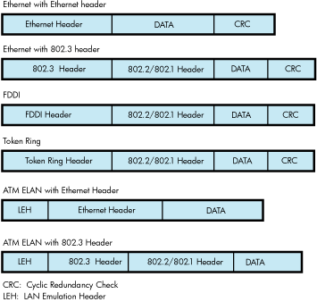
The frame formats available in the LAN media are
shown in Figure 9-1.
Figure 9-1 LAN Frame Formats
Note that Ethernet provides two frame formats
and the FDDI provides one frame format. The 802.1 header is an optional
extension to the 802.2 header.
9.4.6.1 Ethernet Frames
There are two headers for Ethernet frames:
Ethernet header
IEEE 802.3 header
Figure 9-2 illustrates an Ethernet frame with an Ethernet header.
Figure 9-2 Ethernet Frame with Ethernet Header
The Ethernet header consists of the DA, SA, and
PTY fields. Ethernet frames must be at least 64 bytes in length, which
means that the minimum data length is 46 bytes. Applications select
Ethernet format by specifying NMA$C_LINFM_ETH (the default) as the
value for NMA$C_PCLI_FMT in their P2 characteristics buffer. If the
amount of actual data to be transmitted is less than 46 bytes, the
Ethernet drivers transmit extra bytes of zero after the application
data.
Figure 9-3 illustrates a Ethernet frame with an IEEE 802.3 header.
Figure 9-3 Ethernet Frame with IEEE 802.3 Header
The IEEE 802.3 format is similar to the Ethernet
format, except the PTY field is replaced by the LEN field.
The FDDI header consists of the FC, DA, and SA
fields.
9.4.6.3 Token Ring Frames
Figure 9-5 illustrates the format of Token Ring frames.
Figure 9-5 Token Ring Frame Format
9.4.6.4 ATM ELAN Frames
Figure 9-6 illustrates the format of LAN emulation data frame format for the
IEEE 802.3 and Ethernet Header.
Figure 9-6 LAN Emulation Data Frame Format with IEEE 802.3/Ethernet Header
9.4.6.5 Ethernet (Ethernet Version 2, DIX)
Frame Format
The Ethernet format specifies a two-byte protocol
type field followed by an optional length field. The length field
is included in transmit packets and expected in receive packets with
the PAD parameter is enabled. The following sections describe these
features.
9.4.6.5.1 Ethernet Protocol Types
Every Ethernet frame has a 2-byte protocol type
field. This field is used to determine the port to which a packet
belongs. When an application starts a port, it specifies the protocol
type to be used on that port. Packets sent over that port always
have the protocol type inserted in the packet header by the LAN driver,
and packets received for that protocol type are delivered to the application
that owns the port. Valid protocol types are in the range 05-DD through
FF-FF.
The following lists the cross-company protocol
types:
Value
Meaning
08-00
IP protocol
08-06
Address resolution protocol (ARP)
86-DD
IP protocol Version 6
(IPV6)
90-00
Ethernet Loopback protocol
The following list some commonly used protocol
types.
Value
Meaning
60-01
DNA Dump/load (MOP)
60-02
DNA Remote Console (MOP)
60-03
DNA Routing
60-04
Local Area Transport
(LAT)
60-05
Diagnostics
60-06
Customer use
60-07
System Communication
Architecture (SCA)
80-38
Bridge
80-3C
DNA Naming Service
80-3D
CSMA/CD Encryption
80-3E
DNA Time Service
80-3F
LAN Traffic Monitor
80-40
NETBIOS Emulator (PCSG)
80-41
Local Area System Transport (LAST)
9.4.6.6 802 (IEEE 802.x LLC) Frame Format
The IEEE 802 packet formats accepted for a port
depend on the service enabled on that port. All 802 packet formats
have an 802.2 header. The service on the port determines the valid
values for the 802.2 fields.
When a port is started, the NMA$C_PCLI_SRV parameter
in the P2 buffer selects the service on that port. A value of NMA$C_LINSR_CLI
specifies Class I service and a value of NMA$C_LINSR_USR specifies
er-supplied service (the default).
9.4.6.6.1 802 Service Access Point (SAP) Types
Every IEEE 802 frame has a 1-byte Service Access
Point (SAP) field. This field identifies where the packet came from,
the source port on the sending node. And it identifies the destination
port for the packet on the receiving node. When an application starts
a port, it specifies the SAP value that identifies the port. Packets
sent over that port always have SAP value inserted into the SSAP field
in the packet header by the LAN driver, and packets received for the
SAP value in the DSAP field are delivered to the application that
owns the port. Also, when transmitting a packet, the application
specifies the destination SAP value, in addition to the destination
address. And when receiving a packet, the application is given the
source SAP value as well as the source address.
The following lists some commonly used SAP values.
Value
Meaning
FE
DECnet-V Link State Routing
F0
Pathworks
9.4.6.6.2 Class I Service Packet Format
For
Class I service, only three packet formats are transmitted and received:
UI, XID, and TEST. Figure 9-7 shows the 802.2 header format for Class I service.
Figure 9-7 Class I Service 802.2 Header
The control field for an 802 packet is always
an unnumbered control field. The unnumbered control field, which is
always 1 byte in length, is passed by the P4 argument of the write
QIO and can be one of the following binary values:
UI command (00000011)
This is the unnumbered information command. It
is the method used to transmit data from one user to another and is
the most widely used control field value.
The UI command can be specified by using NMA$C_CTLVL_UI.
XID command (101p1111)
This is the exchange identification command. It
is used to convey information about the port. The “p”
bit is the poll bit and can be either 0 or 1. This command can be
specified by using NMA$C_CTLVL_XID for a “0” poll bit
or NMA$C_CTLVL_XID_P for a “1” poll bit.
XID response (101f1111)
The XID response is a response to an XID command.
The “f” bit is the final bit and matches the poll bit
from the XID command.
TEST command (111p0011)
The TEST command is used to test a connection.
The “p” bit is the poll bit and can be either 0 or 1.
This command can be specified by using NMA$C_CTLVL_TEST for a “0”
poll bit or NMA$C_CTLVL_TEST_P for a “1” poll bit.
TEST response (111f0011)
The TEST response is a response to a TEST command.
The “f” bit is the final bit and matches the poll bit
from the TEST command.
An 802 format port with Class I service is allowed
to transmit UI, XID, and TEST commands. An 802 format port with Class
I service is allowed to receive UI commands and XID and TEST responses.
For more information on these control field values
and response messages, see the IEEE 802.2 Standard.
9.4.6.6.3 User-Supplied Service Packet Format
The user provides the control field values, which
are documented in the IEEE 802.2 Standard. The user-supplied packet
format is the generic packet format as specified in the IEEE 802.2
Standard. Class I packets (see “Class I Service Packet Format” ) are a subset of this generic packet
format; therefore, if the control field value of the user-supplied
packet is UI, XID, or TEST, the packet is the same as a Class I packet.
Note that Class II packets, as defined in the IEEE 802.2 Standard,
include the UI, XID, and TEST command/response formats.
9.4.6.6.4 Service Access Point (SAP) Use and Restrictions
The IEEE 802.2 Standard
places restrictions on both user SAPs and source SAPs (SSAPs). All
SAPs are 8 bits long. Figure 9-8 shows the format of destination SAPs (DSAPs) and SSAPs.
Figure 9-8 DSAP and SSAP Format
Definition of the least significant bit depends
on whether the SAP is a source SAP (SSAP) or a destination SAP (DSAP).
For a DSAP field, the least significant bit distinguishes group SAPs
(bit 0 = 1) from individual SAPs (bit 0 = 0). For an SSAP field, the
least significant bit distinguishes commands (bit 0 = 0) from responses
(bit 0 = 1). Because these two bits are located at the same bit position
within the SAP field, a group SAP cannot be used as an SSAP. If this
were allowed, a group SAP would be interpreted as an individual SAP
with the command/response bit set to 1, thus implying a response.
The IEEE 802.2 Standard reserves for its own definition all SAP addresses
with the second least significant bit set to 1. You should use these
SAP values for their intended purposes, as defined in the IEEE 802.2
Standard.
Up to four group SAPs can be enabled on each 802
port. The group SAPs enabled on a controller do not have to be unique
for each port; for example, two 802 format ports can have the same
group SAP enabled. This allows a single packet coming into the controller
to be duplicated and passed to each port on the controller that has
the group SAP enabled—assuming the packet has a DSAP value
that is a group SAP. If the received packet has an individual SAP
for a DSAP, the packet goes to, at most, one port.
9.4.6.7 802 Extended (IEEE
802.x LLC/SNAP) Frame Format
The
802E format uses the 802.2 and 802.1 headers, as shown in Figure 9-9.
Figure 9-9 802 Extended Header
For an 802E packet format, the DSAP
and SSAP fields are always set to the SNAP SAP (AA hex). The SNAP
SAP value is a special SAP value reserved for 802 extended format
packets. The SNAP SAP value distinguishes an 802 packet from an 802
extended packet. The only valid control field value for 802 extended
packets is UI (unnumbered information).
9.4.6.7.1 802E PID Types
Every SNAP frame has a 5-byte protocol ID (PID)
field. This field is used to determine the port to which a packet
belongs. When an application starts a port, the it specifies the
PID to be used on that port. Packets sent over that port always have
the PID inserted in the packet header by the LAN driver, and packets
received for that PID are delivered to the application that owns the
port.
The following lists the cross-company PID values.
Value
Meaning
08-00-2B-90-00
Loopback protocol
The following lists some commonly used PID values.
Value
Meaning
08-00-2B-60-02
Loopback protocol
08-00-2B-60-01
DNA Dump/load (MOP)
08-00-2B-60-02
DNA Remote Console (MOP)
08-00-2B-80-3C
DNA Naming Service
08-00-2B-80-3E
DNA Time Service
08-00-2B-80-48
Availability Manager (AMDS)
9.4.7 Packet Padding
This section describes the PAD parameter NMA$C_PCLI_PAD,
which is used only in the Ethernet packet format.
All Ethernet frames must be at least 64 bytes
in length. This includes the Ethernet header, the user data, and the
CRC. If the user data, CRC, and Ethernet header together are less
than 64 bytes, zero padding bytes are inserted between the user data
and the CRC to make a 64-byte packet. This packet padding cannot be
turned off.
The PAD parameter directs the LAN drivers to place
a data-size field in the packet between the standard header and the
user data. If padding is on (NMA$C_STATE_ON is specified), a 2-byte
length field is inserted after the Protocol Type field and before
the user data.
If the PAD parameter is off (NMA$C_STATE_OFF is
specified), Ethernet packets have the following characteristics:
Packets transmitted are
padded with null bytes as needed (CSMA/CD only).
Packets transmitted do
not include the size field.
The length of user data
in the packets received is always between 46 and 1500 bytes (9000
bytes for jumbo frames) for CSMA/CD, and 0 to 4470 for FDDI. For example,
if a 10-byte packet is transmitted, it is received as 46 bytes because
the driver cannot determine the amount of user data in the packet—only
the amount of user data plus padded null bytes.
If the PAD parameter is on (NMA$C_STATE_ON is
specified), Ethernet packets have the following characteristics:
Packets transmitted are
padded with null bytes as needed (CSMA/CD only).
Packets transmitted include
the size field.
The length of user data
in the packets received is always between 0 and 1498 bytes (8998 bytes
for jumbo frames) for CSMA/CD, and 0 to 4468 bytes for FDDI. The driver
uses the size field to determine the amount of user data in the packet.
The size field is not included in the data returned to the user.
9.4.8 Protocol Type and PID Sharing
Protocol
types and PIDs are usually nonshareable; however, an application may
benefit from a shared protocol implementation. The protocol access
parameter (NMA$C_PCLI_ACC) allows a protocol type or PID to be opened
in either of two shareable modes: shared-default (NMA$C_ACC_SHR) and
shared-with-destination (NMA$C_ACC_LIM).The LAN drivers also provide
the nonshareable exclusive mode (NMA$C_ACC_EXC). (See Table 9-33.) The rules and
requirements for using each mode are as follows:
The exclusive mode is
the default if no access mode is supplied as a P2 buffer parameter.
This mode of operation does not allow the protocol to be shared by
other users. Any attempt to start up another protocol of the same
type results in an error status of SS$_BADPARAM.
The shared-with-destination
mode is a protocol type or PID/destination address pairing that allows
multiple users to share a protocol type or PID and to communicate
with a different node.
For a given shared
protocol type or PID, there can be many “shared-with-destination”
users; each user communicates with a different destination address.
Any attempt to start a port with a destination address that is in
use results in an error status of SS$_BADPARAM.
When a “shared-with-destination”
user passes the set mode P2 buffer, the buffer must contain a destination
address in the NMA$C_PCLI_DES parameter. This destination address
is used as the destination address in all messages transmitted, and
the user receives messages only from this address.
The shared-default mode
is the default user of a shared protocol type or PID. There can be
only one such user for each shared protocol type or PID. A “shared-default”
user does not have to exist if a protocol type or PID is shared, but
there can be no more than one such user per shared protocol type or
PID.
The “shared-default”
user receives all messages for the shared protocol type or PID, but
not for any of the “shared-with-destination” users.
The “shared-default” user also receives all messages
matching both the shared protocol type or PID and any multicast address
enabled by the “shared-default” user.
The “shared-default” user can only
transmit to multicast addresses and physical addresses that are not
enabled by any of the “shared-with-destination” users
sharing the same protocol type or PID.
If there is no “shared-default”
user of a protocol type or PID, incoming messages from nodes not among
the “shared-with-destination” users for that protocol
type or PID are ignored.