The LAN drivers can perform logical,
virtual, and physical I/O operations. The basic functions are read,
write, set mode, set characteristics, sense mode, and sense characteristics. Table 9-28 lists these functions
and their codes. The following sections describe these functions in
greater detail.
Sense controller characteristics
and return them in specified buffer.
[1] V= virtual, L=logical, P=physical ( There is no functional difference
in these operations.)
[2] On OpenVMS Alpha and Integrity servers , P1 and P5 support 64-bit
addresses.
[3] On OpenVMS Alpha, P1, P4, and P5 support 64-bit address.
[4] The P1 and P3 arguments are only for attention AST QIOs.
Note
that the LAN device drivers do not differentiate among logical, virtual,
and physical I/O functions; all are treated identically.
9.7.1 Read
Read
functions directly transfer data from a packet received from another
port on the Ethernet into the virtual memory address space of the
user process. The operating system provides the following function
codes:
IO$_READLBLK—Read
logical block
IO$_READVBLK—Read
virtual block
IO$_READPBLK—Read
physical block
Received messages are buffered in system memory
and then copied to the user's buffer when a read operation is
performed.
The read functions take the following device-
or function-dependent arguments:
P1—The starting
virtual address of the buffer that is to receive data. On OpenVMS
Alpha and Integrity server systems, P1 can be a 64-bit address.
P2—The size of
the receive buffer in bytes.
P5—The address
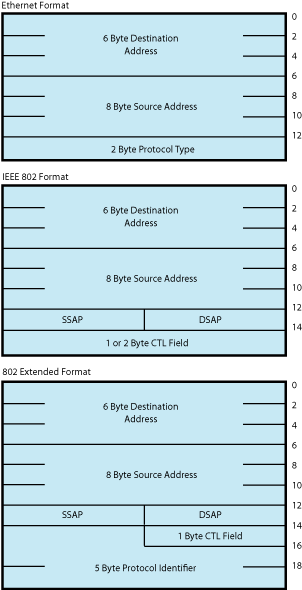
of a buffer where the LAN driver returns packet header information.
This is an optional argument. The information returned depends on
the packet format enabled with the set mode QIO. The size of the buffer
must be 14 bytes for an Ethernet format packet, 16 bytes for an IEEE
802 format packet, and 20 bytes for an 802 extended format packet.
Note that the information returned is not the entire packet header
but the header information less any length or size fields. The IOSB,
if specified, is where the packet length information is returned.
For FDDI, if received access control (RAC) is on, then 1 byte must
be added to these sizes.
For Token Ring,
this buffer must be at least 54 bytes in length due to a possible
variable length source routing header.
If NMA$C_PCLI_PRM (see Table 9-33) is enabled, the
P5 buffer must be at least 20 bytes for Ethernet and 21 bytes for
FDDI. Figure 9-12 shows the format
of the three buffers. On OpenVMS Alpha and Integrity server systems,
P5 can be a 64-bit address.
Figure 9-12 Read Function P5 Buffer
The P1 and P2 arguments must always be specified;
the P5 argument is optional. However, if P5 is not specified, you
will not be able to determine the source of the received message .
If the size of the user data in a receive message
is larger than the value of the NMA$C_PCLI_BUS parameter, the message
is not given to the user, even if there is sufficient space in the
user's receive buffer.
If the size of the user data in a receive message
is larger than the size specified in P2 (and less than or equal to
the value of the NMA$C_PCLI_BUS parameter), the P1 buffer is filled
and SS$_DATAOVERUN is returned in the I/O status block.
Table 9-29 lists the maximum user data sizes that can be received for Ethernet,
FDDI, and Token Ring protocols.
Table 9-29 Maximum User Data Sizes for Ethernet, FDDI, and Token Ring
Packet Format
Ethernet
FDDI
Token Ring
Ethernet
format without padding
1500
4470
4418
Ethernet
format with padding
1498
4468
4416
802
format with 1-byte CTL field
1497
4475
4423
802
format with 2-byte CTL field
1496
4474
4422
802E format
1492
4470
4418
Table 9-30 lists the maximum user data sizes that can be received for LAN
emulation over ATM protocol.
Table 9-30 Maximum User Data Sizes for LAN Emulation over ATM
Packet Format
ATM ELAN size:
1516
4544
9234
Ethernet
format without padding
1500
4528
9218
Ethernet
format with padding
1498
4526
9216
802
format with 1-byte CTL field
1497
4525
9215
802
format with 2-byte CTL field
1496
4524
9214
802E format
1492
4520
9210
For 802 format packets, the P5 buffer always contains
the DSAP and SSAP in the bytes at offset 12 and 13. The next one or
two bytes (offsets 14 and 15) following the SSAP contain the control
field value. For Class I service, the control field value is always
1 byte in length and is always placed in the byte at offset 14 of
this buffer. For user-supplied service, you have to determine the
length of the control field value according to the IEEE 802.2 Standard.
For Token Ring, if received access control (RAC)
is on, the first byte of the P5 buffer contains the frame control
(FC) field.
For FDDI, if RAC is on, the first byte of the
P5 buffer contains the FC field.
The read functions can take the following function
modifier:
IO$M_NOW—Complete
the read operation immediately with a received message (if no message
is currently available, return a status of SS$_ENDOFFILE in the I/O
status block).
9.7.2 Write
Write functions provide for the direct transfer of data
from the virtual memory address space of the user process to the communications
medium. The operating system provides the following function codes:
IO$_WRITELBLK—Write
logical block
IO$_WRITEVBLK—Write
virtual block
IO$_WRITEPBLK—Write
physical block
Transmitted messages are copied from the buffer
of the requesting process to a system buffer for transmission.
The write function takes the following device-
or function-dependent arguments:
P1—The starting
virtual address of the buffer containing the data to be transmitted.
On OpenVMS Alpha and Integrity server systems, P1 can be a 64-bit
address.
P2—The size of
the buffer in bytes.
P4—The address
of a quadword that points to a buffer that contains the DSAP and CTL
field values (optional). (See “Service Access Point (SAP) Use and Restrictions”.) The first longword is the buffer
length; the second longword is the address of the buffer. This argument
is used only for ports with the 802 packet format. The format of the
buffer is:
On OpenVMS
Alpha and Integrity server systems, P4 can be a 64-bit address.
P5—The address
of a 6-byte buffer that contains the destination address. For FDDI,
if XFC is specified as zero on startup, the first byte of the P5 buffer
contains the low-order 3 bits of the FC field to be transmitted. On
OpenVMS Alpha and Integrity server systems, P5 can be a 64-bit address.
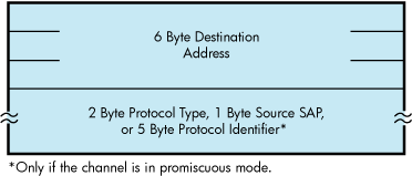
If the device is in promiscuous mode (NMA$C_PCLI_PRM;
see Table 9-33), you
must pass a larger buffer with additional information positioned after
the destination address. For Ethernet packet format, the buffer must
be 8 bytes with the 2-byte protocol type following the destination
address. For 802 packet format, the buffer must be 7 bytes with the
1-byte source SAP following the destination address. For 802 extended
packet format, the buffer must be 11 bytes with the 5-byte protocol
identifier following the destination address. The Source SAP cannot
be a group SAP or the SNAP SAP. Figure 9-13 shows the format of the P5 buffer. For FDDI
with XFC specified as zero on startup, 1 byte must be added to these
sizes for the FC field.
Figure 9-13 Write Function P5 Buffer
Table 9-31 lists the maximum user data sizes that can be specified by P2 and
received for Ethernet, FDDI, and Token Ring protocols.
Table 9-31 Maximum Message Sizes for Ethernet, FDDI, and Token Ring
Packet Format
Ethernet
FDDI
Token Ring
Ethernet
format without padding
1500
4470
4418
Ethernet
format with padding
1498
4468
4416
802
format with 1-byte CTL field
1497
4475
4423
802
format with 2-byte CTL field
1496
4474
4422
802E format
1492
4470
4418
Table 9-32 lists
the maximum user data sizes that can be specified by P2 and received
for LAN emulation over ATM protocol.
Table 9-32 Maximum Message Sizes for LAN Emulation over ATM
Packet Format
ATM ELAN size:
1516
4544
9234
Ethernet
format without padding
1500
4528
9218
Ethernet
format with padding
1498
4526
9216
802
format with 1-byte CTL field
1497
4525
9215
802
format with 2-byte CTL field
1496
4524
9214
802E format
1492
4520
9210
If P2 specifies a message size larger than that
allowed, the driver returns the status SS$_IVBUFLEN in the I/O status
block.
If the P4 buffer is specified, it must
be at least 3 bytes long. The first byte is always the DSAP; the next
two bytes are used to determine the CTL field value. The DSAP value
cannot be the SNAP SAP.
The CTL field value is either a 1-byte or 2-byte
value. If the two least significant bits of the low-order byte of
the CTL field contain the bit values 11, just the low-order byte of
the CTL field is used as the CTL field value. Otherwise, both bytes
of the CTL field are used as the CTL field value.
If the driver uses only the low-order byte of
the CTL field, you still must pass at least a 3-byte buffer. In this
case, the driver uses the low-order byte of the CTL field and ignores
the high-order byte.
If Class I service is enabled, only 1-byte CTL
field values can be passed. If user-supplied service is enabled, then
both 1- and 2-byte CTL field values are valid. If Class I service
is enabled, the CTL field value must be one of the three command values:
UI, XID, or TEST.
Regarding 802 ports, you can receive packets for
the SAP enabled with the IO$_SETMODE or IO$_SETCHAR QIOs and can transmit
packets destined for a different SAP. This is similar to an Ethernet
port receiving packets for one protocol type and transmitting packets
with a different protocol type (which is not possible with the current
Ethernet $QIO interface). It is expected that most 802 format applications
wants to process only receive packets from a source SAP that matches
the SAP enabled on their port. To do this, the read function (see “Read”) has been
enhanced to return the source SAP to you. To verify that the source
SAP of an incoming packet matches the SAP enabled on the port, you
need only match the source SAP returned by the read function with
the SAP enabled on the port.
The write function can take the following function
modifier:
IO$M_RESPONSE—Transmit
a response packet (sets the low-order bit in the SSAP field). This
allows users with user-supplied service enabled to respond to certain
802 format command packets. IO$M_RESPONSE can be specified only when
you have the 802 packet format enabled. The 802 packet format ports,
with Class I service enabled, result in an error if you attempt to
transmit a response message with a CTL field value of unnumbered information
(UI).
9.7.3 Set Mode and Set Characteristics
The operating system provides the following two
function codes:
IO$_SETMODE
IO$_SETCHAR
Other than the privilege check, these two function
codes are treated the same by the LAN drivers. This section refers
to the IO$_SETMODE function code only, even though applications can
use either function code.
The set mode function code is used to perform
many different functions. These different functions are distinguished
by the modifiers set with the function code. The LAN drivers support
the following set mode requests:
IO$_SETMODE!IO$M_CTRL
— Set or modify port attributes
IO$_SETMODE!IO$M_CTRL!IO$M_STARTUP
— Set port attributes and start port
IO$_SETMODE!IO$M_SET_MAC
— Set medium attributes
IO$_SETMODE!IO$M_CTRL!IO$M_SHUTDOWN
— Shut down port
IO$_SETMODE!IO$M_ATTNAST
— Enable attention AST
IO$M_SETMODE!IO$M_UPDATE_MAP
— Update functional address mapping table (Token Ring only)
IO$M_SETMODE!IO$M_ROUTE
— Update source routing cache table (Token Ring only)
The following sections describe these functions
in detail.
9.7.3.1 Set Controller Mode
Once a port is created using the $ASSIGN system
service, you can set the port attributes and start the port using
the requests listed in the previous section. Note that in most cases
only IO$_SETMODE!IO$M_CTRL!IO$M_STARTUP is issued because it sets
the port attributes and starts the port with one request. IO$_SETMODE!IO$M_CTRL
is most often used to modify port attributes after the port has been
started.
If the function modifier IO$M_STARTUP is specified,
the LAN port is started. If IO$M_STARTUP is
not specified, the specified characteristics are modified.
This function takes the following device- or function-dependent
argument:
P2—The address
of a quadword descriptor for an extended characteristics buffer. The
first longword of the descriptor is the buffer length; the second
longword is the address of the buffer. The P2 argument is optional.
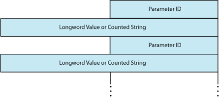
The P2 buffer consists of a series
of 6-byte or counted string entries. The first word of each entry
contains the parameter identifier (ID) of an attribute, followed by
either a longword that contains one of the (binary) values that can be associated with
the parameter ID or a counted string. Counted strings consist of a
word that contains the size of the character string followed by the
character string. Figure 9-14 shows
the format for this buffer.
Figure 9-14 P2 Extended Characteristics Buffer
Table 9-33 is an alphabetic
listing of the parameter IDs and values that can be specified in the
P2 buffer. These parameter IDs are applicable to all LAN controllers,
except where otherwise noted. The $NMADEF macro defines these values.
The $NMADEF macro is included in the macro library SYS$LIBRARY:LIB.MLB.
(Table 9-33 lists the
parameters that can be used with each of the packet formats, and indicates
which are required, which are optional, and which generate the SS$_BADPARAM
error.)
If the status SS$_BADPARAM is returned in the
first word of the I/O status block, the second longword contains the
parameter ID of the parameter in error.
Table 9-33 P2 Attributes
Parameter ID
Meaning
NMA$C_PCLI_ACC
Protocol access mode. This optional parameter
determines the access mode for the protocol type. NMA$C_PCLI_ACC
is valid only for ports using Ethernet packet format.
NMA$C_PCLI_ACC is valid for ports using 802E packet format.
Number of receive buffers to preallocate
(default = 1). NMA$C_PCLI_BFN can have a maximum value of 255. This
optional parameter is specified on a per-port basis.
NMA$C_PCLI_BFN
is passed as a longword value.
NMA$C_PCLI_BFN represents
the number of receive messages the LAN driver holds for a port when
the port has no read QIOs posted to the driver.
NMA$C_PCLI_BUS
Any message received for this port that is larger
than this parameter value is discarded.
Maximum allowable
port receive data size, that is, message length (default = 512 bytes).
NMA$C_PCLI_BUS can have a maximum value of 9234.This optional parameter
is specified on a per-port basis. It is passed as a longword value.
NMA$C_PCLI_CCA
Can change address. This optional parameter enables
applications to start before DECnet starts. DECnet may attempt to
set the physical address of the controller when it starts. Ethernet
devices support only one physical address, and so all applications
that are using the same device must also use the same physical address.
If applications that do not use the DECnet address start before DECnet,
DECnet is not able to start on that controller unless the other applications
that have already started have all specified NMA$C_PCLI_CCA to be
ON.
This parameter is not applicable to FDDI because FDDI
devices can run with more than one physical address; however, no error
is returned if this parameter is supplied for FDDI devices. The application
receives no indication whatsoever that the physical address has changed.
This parameter is passed as a longword. One of the following values
can be specified:
NMA$C_STATE_ON — The physical address can be
changed.
NMA$C_STATE_OFF — The physical address cannot
be changed (default).
Controller mode.
This optional parameter determines whether transmit packets are to
be looped back at the controller. One of the following values can
be specified:
NMA$C_LINCN_NOR — Normal mode (default)NMA$C_LINCN_LOO
— Loopback mode
The only messages looped back are those
acceptable to the controller as receive messages, that is, those messages
that possess at least one of the following characteristics:
Cyclic redundancy
check (CRC) generation state for transmitted messages (optional).
One of the following values can be specified:
NMA$C_STATE_ON
— Controller generates a CRC (default).NMA$C_STATE_OFF —
Controller does not generate a CRC.NMA$C_PCLI_CRC affects all ports
on a single controller. There is no effect onchecking a receive message’s
CRC (it is always checked). NMA$C_PCLI_CRC is passed as a longword
value.
If NMA$C_PCLI_CRC is turned off, all users
of the controller must supply the 4-byte CRC value for all messages
transmitted. The CRC is passed at the end of the P1 transmit buffer;
the additional 4 bytes are included in the size of the P1 buffer.
The CRC value is not checked for correctness.
For the
DEQNA, DELQA, and Token Ring devices, the NMA$C_PCLI_CRC parameter
cannot be turned off.
For the DEQNA, DELQA, and Token
Ring devices, the NMA$C_PCLI_CRC parameter cannot be turned off.
Not all devices support user-supplied CRC. If a controller-generated
CRC is specified, the request is completed with SS$_BADPARAM status.
NMA$C_PCLI_DES
Shared protocol destination address. Passed
as a counted string that consists of a modifier word (NMA$C_LINMC_SET
or NMA$C_LINMC_CLR) followed by a 6-byte (48-bit) physical destination
address. The size of the counted string must always be 8. NMA$C_PCLI_DES
only has meaning when protocol access (NMA$C_PCLI_ACC) is defined
as shared-with-destination mode (NMA$C_ ACC_LIM). The destination
address specified must be a physical address—not a multicast
address—and it must be unique among all ports sharing the same
protocol. NMA$C_PCLI_DES is required when the access mode is defined
as ‘‘shared-with-destination.’’
NMA$C_PCLI_DES should not be specified on a port where the
802 or 802E packet format is selected (NMA$C_PCLIFMT is set to NMA$C_LIFM_802
or NMA$C_LIFM_802E). For 802 packet format, the concept of shared
protocol type is handled by using group SAPs.
NMA$C_PCLI_DES
should not be specified on a port where the 802 packet format is selected
(NMA$C_PCLIFMT is set to NMA$C_LIFM_802). For 802 packet format, the
concept of shared protocol type is handled by using group SAPs.
Echo mode.
Applicable only to the DEUNA device driver.
If echo mode
is on, transmitted messages are returned to the sender. This optional
parameter controls the condition of the half-duplex bit in the DEUNA
mode register. One of the following values can be specified:
NMA$C_STATE_OFF — Does not echo transmit messages (default)
NMA$C_STATE_ON — Echoes transmit messages
If NMA$C_STATE_ON is specified, the only
transmitted messages echoed are those acceptable to the DEUNA as receive
messages, that is, those messages that have at least one of the following
characteristics:
Promiscuous mode (NMA$C_PCLI_PRM) is in the ON state
Destination address is a multicast address and all
multicasts are enabled (NMA$C_PCLI_MLT is in the ON state)
If the DEUNA is placed in loopback mode
(NMA$C_LINCN_LOO is specified in the NMA$C_PCLI_CON parameter), the
driver enables echo mode.
NMA$C_PCLI_EKO affects all ports
on a single controller. It is passed as a longword value.
NMA$C_PCLI_FMT
Packet format. This optional parameter specifies
the packet format as either Ethernet, IEEE 802, or 802 extended. This
characteristic is passed as a longword value and affects single ports
on a single controller. One of the following values can be specified:
NMA$C_LINFM_ETH — Ethernet packet format (default)
NMA$C_LINFM_802 — 802 packet format NMA$C_LINFM_802E —
802 extended packet format
NMA$C_PCLI_PTY, NMA$C_PCLI_ACC, and NMA$C_PCLI_DES
should only be specified on those ports where the Ethernet packet
format (NMA$C_LINFM_ ETH) is selected.
NMA$C_PCLI_SRV,
NMA$C_PCLI_SAP, and NMA$C_PCLI_GSP should only be specified on those
ports where the 802 packet format (NMA$C_LINFM_802) is selected.
NMA$C_PCLI_PID should only be specified on those ports where
the 802 extended packet format (NMA$C_LINFM_802E) is selected.
NMA$C_PCLI_GSP
Group SAP. This is an optional parameter
if the 802 packet format is selected (NMA$C_PCLIFMT is set to NMA$C_LINFM_802).
If the Ethernet or 802 extended packet format is selected, NMA$C_PCLI_GSP
cannot be specified. Group SAPs can be shared among multiple ports
on the same controller. If the 802 packet format is selected, NMA$C_PCLI_GSP
defines up to four 802 group SAPs that are to be enabled for matching
incoming packets to complete read operations on this port. By default,
no group SAPs are enabled.
NMA$C_PCLI_GSP is passed as
a longword value and is read as four 8-bit unsigned integers. Each
integer must be either a group SAP or zero. To enable a single group
SAP on a port, you need only specify the group SAP value to be enabled
in one of the four integers and place a value of zero in the three
remaining integers. To disable group SAPs on the port, you need only
place a value of zero in all four integers and issue the QIO.
If this characteristic is correctly specified, any group SAPs
that were previously enabled on the port are now replaced by the SAPs
specified by the current request.
Internal
loopback mode. This optional parameter places the device in internal
loopback mode (not for the DEUNA, DEQNA, or DELQA devices). One of
the following values can be specified:
NMA$C_STATE_ON — Internal loopback mode
NMA$C_STATE_OFF — Not in internal loopback mode (default)
If NMA$C_STATE_ON is specified, the NMA$C_PCLI_CON
parameter must be in loopback (NMA$C_LINCN_LOO) mode.
When the controller is in loopback mode (generally for testing),
it can loop packets in external loopback or internal loopback. This
parameter places the controller in one of these loopback modes. NMA$C_PCLI_ILP
is passed as a longword value and affects all ports on the controller.
Not all devices support loopback mode. If NMA$C_STATE_OFF is
not specified, the request is completed with SS$_BADPARAM status.
NMA$C_PCLI_MCA
Multicast address (optional). Passed as a
counted string that consists of a modifier word followed by a list
of 6-byte (48-bit) multicast addresses. The value specified in the
modifier word determines whether the addresses are set or cleared.
If NMA$C_LINMC_CAL is specified, all multicast addresses in the list
are ignored.
The following mode values can be specified
in the low byte of the modifier word:
NMA$C_LINMC_SET — Set the multicast addresses.
NMA$C_LINMC_CLR — Clear the multicast addresses.
NMA$C_LINMC_CAL — Clear all multicast addresses.
The driver filters all multicast addresses on a
per-port basis; therefore, only messages received with the port's
physical address or the multicast addresses enabled on the port are
used to complete the user's read operations.
Note
that each LAN controller supports a limited number of multicast addresses.
If this limit is exceeded, the LAN driver enables the “accept
all multicast” feature on the controller and all multicast
packets on the LAN must be filtered by the LAN driver. This may cause
a minor performance loss.
NMA$C_PCLI_MCA is specified
on a per-port basis.
NMA$C_PCLI_MLT
Multicast address state. This optional
parameter instructs the controller hardware whether to accept all
multicast addresses for this port. One of the following values can
be specified:
NMA$C_STATE_ON — Accept all multicast addresses.NMA$C_STATE_OFF
— Do not accept all multicast addresses (default).
NMA$C_PCLI_MLT allows you to receive all multicast
address packets that also match the port's protocol type, SAP,
or protocol identifier.
Generally, you enable only your
individual set of multicast addresses using the NMA$C_PCLI_MCA parameter,
and leave the NMA$C_PCLI_MLT parameter in the off state.
There could be a minor performance loss when the NMA$C_PCLI_MLT parameter
is in the ON state because the LAN driver may have to process all
multicast addresses on the medium; the number of multicast addresses
on the line determines the amount of processing required.
The NMA$C_PCLI_MLT parameter is passed as a longword value.
NMA$C_PCLI_PAD
Use message size field on transmit and receive messages
(optional). One of the following values can be specified:
NMA$C_STATE_ON — Insert message size field (default)
NMA$C_STATE_OFF — No size field
NMA$C_PCLI_PAD affects only the protocol type that
issued the set mode request. It is passed as a longword value.
On Ethernet, if padding is enabled on Ethernet format packets,
the driver adds a 2-byte count field to the transmitted data. This
field allows short packets (packets fewer than 46 bytes long) to be
received with the proper length returned by the driver. The minimum
Ethernet packet contains 46 bytes of user data. When fewer than 46
bytes are sent, the packet is padded and the receiver always receives
46 bytes of data. When padding is enabled, the maximum message size
for transmit or receive operations is 1498 bytes (8998 bytes for jumbo
packets) and the minimum is zero bytes. See “Ethernet Protocol Types” for additional information. NMA$C_PCLI_PAD
should be specified only on a port where the Ethernet packet format
is selected (NMA$C_PCLI_FMT is set to NMA$C_LINFM_ETH).
For FDDI, the same 2-byte count field is added; however, because
FDDI packets can be as short as 22 bytes, FDDI transmit requests are
never padded.
Physical address
(optional). It is passed as a counted string that consists of a modifier
word followed by the 48-bit physical address. If the request is to
clear the physical address or to set the physical address to the default
address, the physical address (if present) is not read.
One of the following mode values can be specified in the low byte
of the modifier word:
NMA$C_LINMC_SET — Set the string value.
NMA$C_LINMC_CLR — Clear the physical address.
NMA$C_LINMC_SDF — Set the physical address to the default
address. For CSMA/CD, the default address is constructed by appending
the low-order word of the system parameter SCSSYSTEMID to the constant
DECnet header (AA-00-04-00). If SCSSYSTEMID is zero, and NMA$C_LINMC_SDF
is specified, the hardware address is used as the default.
If not specified for Ethernet, the default is the
current address set by a previous set mode function on this controller,
or the hardware address if no address was defined by a previous set
mode function. If not specified for FDDI, the default is the hardware
address.
The physical address must be passed as a 6-byte
(48-bit) quantity. The first byte is the least significant byte. A
return value of -1 on a sense mode request implies that a physical
address is not defined.
The NMA$C_PCLI_PHA parameter affects
all ports on a single controller. If the address specified is already
being used on the extended LAN, SS$_IVADDR is returned.
NMA$C_PCLI_PID
Protocol identifier. This parameter is required
for, and valid only on, ports that use 802 extended format packets.
NMA$C_PCLI_PID is passed as a counted 5-byte string, which is the
unique protocol identifier required for each 802 extended format user.
All protocol identifiers specified on a controller must be
unique except when the PID is being shared.
NMA$C_PCLI_PID
may only be specified on a port when the 802 extended packet format
is selected; that is, NMA$C_PCLIFMT is set to NMA$C_LIFM_802E.
NMA$C_PCLI_PRM
Promiscuous (optional). One of the following
values can be specified:
NMA$C_STATE_ON—Promiscuous mode enabled.
NMA$C_STATE_OFF—Promiscuous mode off.
The NMA$C_PCLI_PRM parameter is passed as a longword
value.
Only one port on each controller can be active
with promiscuous mode enabled. Enabling promiscuous mode requires
PHY_IO privilege.
THe NMA$C_PCLI_PRM parameter is passed
as a longword value.
HP does not recommend promiscuous
mode for normal usage.
Some Token Ring devices do not
support real promiscuous access to the ring.
Protocol type. This value is read as a 16-bit
unsigned integer and must be unique on the controller except when
the protocol type is being shared. For Ethernet format ports, this
is a required parameter.
Valid protocol types are in the
range 05-DD through FF.
NMA$C_PCLI_PTY may only be specified
on a port where the Ethernet packet format is selected (NMA$C_PCLI_FMT
is set to NMA$C_LINFM_ETH).
NMA$C_PCLI_PTY is passed as
a longword value; however, only the low-order word is used.
NMA$C_PCLI_RAC
Receive access control (Token Ring only).
This optional parameter specifies whether the application receives
a copy of the access control (AC) field for each Token Ring frame
received. It is passed as a longword value. It must be passed with
one of the following values:
NMA$C_STAT_ON — Application gets a copy of
the AC for each Token Ring frame received.
NMA$C_STATE_OFF — Application does not get
a copy of the AC for each Token Ring frame received.
The AC is returned in the P5 buffer. The
P5 buffer size for Token Ring should always be a minimum of 54 bytes.
This is due to the variable size of the Token Ring header.
NMA$C_PCLI_RES
Restart. This optional parameter allows the
user to enable the automatic port restart feature of the LAN drivers.
One of the following values can be specified:
The LAN drivers shut down all users of
a controller if there is a fatal error on the controller or if the
LAN driver determines that the controller has stopped functioning.
All outstanding I/O operations on the LAN driver are completed with
either an SS$_ABORT or SS$_TIMEOUT status.
All ports that
have the NMA$C_PCLI_RES parameter enabled (set to NMA$C_LINRES_ENA)
have the port automatically restarted by the LAN driver approximately
one second after it has been shut down due to a fatal error. If the
user issues read or write QIOs to the port during the time the port
is shut down, the driver completes the QIOs with an SS$_OPINCOMPL
status.
All ports that have the automatic restart feature
disabled must be restarted by the application program when the port
is shut down by the LAN driver. The application program should wait
approximately 2 seconds to allow the LAN driver to stabilize. Once
the LAN driver shuts down a port, it attempts a maximum of 30 consecutive
automatic restarts. If there are 30 consecutive failures to restart
the port, the port remains shut down.
Note that it is
unusual to have fatal errors on a LAN controller or to have a LAN
driver detect that a LAN controller has stopped functioning. Having
the ability to automatically restart a user's port makes the
program easier to design because the program does not have to take
into account the possibility of the LAN driver shutting down the port.
NMA$C_PCLL_RFC
Receive frame control (FDDI only). This optional
parameter specifies whether the application receives a copy of the
Frame Control (FC) field for each FDDI frame received. It is passed
as a longword value. However, only the low-order byte is used. It
must be passed with one of the following values:
NMA$C_STATE_ON — Application gets a copy of
the FC for each FDDI frame received.
NMA$C_STATE_OFF — Application gets a copy of
the FC for each FDDI frames (default).
For $QIO Read operations, the FC is passed
to the application in the P5 buffer. The following are the sizes required
for the P5 buffer for various packet formats and settings of NMA$C_PCLI_RFC:
Ethernet (NMA$C_LINFM_ETH) — 14 if NMA$C_STATE_OFF
is specified, 15 if NMA$C_STATE_ON is specified.
802 (NMA$C_LINFM_802) — 16 if NMA$C_STATE_OFF
is specified, 17 if NMA$C_STATE_ON is specified.
802E (NMA$C_LINFM_802E) — 20 if NMA$C_STATE_OFF
is specified, 21 if NMA$C_STATE_ON is specified.
Receiving
the FC requires one additional byte of space in the P5 buffer. The
FC is the first byte in the P5 buffer, immediately preceding the 6-byte
destination address. The size of the P5 buffer required does not change
from the CSMA/CD sizes if NMA$C_PCLI_RFC is set to NMA$C_STATE_OFF.
NMA$C_PCLI_SAP
802 format SAP. This parameter is required
if the 802 packet format is selected (NMA$C_PCLI_FMT is set to NMA$C_LINFM_802)>
NMA$C_PCLI_SAP defines an 802 SAP and is read as an 8-bit unsigned
integer. The least significant bit of the SAP must be 0 and the SAP
cannot be the null SAP (all 8 bits equal 0) or the SNAP SAP. NMA$C_PCLI_SAP
is passed as a longword value. However, only the low-order byte is
used.
The SAP specified by NMA$C_PCLI_SAP is the SAP used
to match incoming packets to complete read requests. It is used as
the source SAP (SSAP) in all transmissions (write QIOs). Because it
is illegal to transmit using a group SAP as the source SAP, the SAP
specified by this NMA$C_PCLI_SAP cannot be a group SAP. NMA$C_PCLI_GSP
describes how to set up group SAPs on a port.
All individual
SAPs specified on a controller must be unique on that controller;
therefore, the SAP specified using the NMA$C_PCLI_SAP parameter is
checked for uniqueness on the controller.
NMA$C_PCLI_SRMODE
Sets the source routing (SR) mode for the
$QIO user (Token Ring only). This optional parameter allows the application
to perform the source routing discovery. It must be passed with one
of the following values:
NMA$C_SR_TRANSPARENT — Application source routing
is transparent. This is the default when this parameter is not specified.
NMA$C_SR_SELF — This shuts off the automatic
route discovery exploration message for this user.
The $QIOs exist to further manipulate
the source routing cache. HP recommends that applications use the
NMA$C_SR_TRANSPARENT mode.
NMA$C_PCLI_SRV
Port service. This optional parameter specifies
the service supplied by the driver for the port. It can only be specified
if the 802 packet format is selected (NMA$C_PCLI_FMT is set to NMA$C_LINFM_802).
This characteristic is passed as a longword value. One of the following
values can be specified:
NMA$C_LINSR_USR — User supplied service (default)
NMA$C_LINSR_CLI — Class I service
NMAC$C_PCLI_XAC
Transmit access control (Token Ring only). This
is an optional parameter that enables applications to control the
setting of the priority bits in the access control (AC) for frames
being transmitted in a $QIO write operations. When set to a wanted
value, all subsequent transmits use this AC value.
NMA$C_PCLI_XFC
Transmit frame control (FDDI) only). NMA$C_PCLI_XFC
is an optional parameter that enables applications to control the
setting of the priority bits in the FC for frames being transmitted
in a $QIO write operation. NMA$C_PCLI_XFC is passed as a longword
parameter that has many valid settings. If specified with a value
of 0, the application supplies an FC value on each $QIO write operation.
The FC value to be used in this case is supplied in the P5 buffer
for the $QIO write operation. If the parameter is specified with a
value other than 0, that value is inserted into the FC field of every
transmit by the FDDI drivers. NO FC is present in the P5 buffer for
the $QIO write in this case. If this parameter is not specified, the
default setting (0) of the priority bits is used.
Regardless
of how the FC is supplied, the value specified must be valid. The
allowable values for FC are between 50 hexadecimal and 57 hexadecimal.
If NMA$C_PCLI_XFC is specified with a nonzero value outside the valid
range, the application receives a SS$_BADPARAM error. The priority
bits are the three low-order bits.
[1] If the LAN controller is active and you do not specify this
parameter, the parameter defaults to current setting. If the LAN controller
is not controller is not active, this parameter defaults to the default
value indicated.
9.7.3.2 Set Mode Parameters for Packet Formats
Table 9-34 summarizes the use of the set mode parameters
for the Ethernet, 802, and 802 extended (802E) packet formats.
When starting a LAN port, the LAN driver checks that the mode of
the new port is compatible with the mode of the LAN ports already
started. There are two sets of compatibility checks: one for ports
running in shared mode and one for all ports.
The following parameters must match for all ports
on the same controller:
NMA$C_PCLI_CON
NMA$C_PCLI_CRC
NMA$C_PCLI_EKO
NMA$C_PCLI_ILP
NMA$C_PCLI_PHA (need only
match for Ethernet controllers)
Once a port is started, only the following parameters
can be changed:
NMA$C_PCLI_GSP
NMA$C_PCLI_MCA
9.7.4 Shutdown Controller
The shutdown controller function shuts down the LAN port.
On completion of a shutdown request all outstanding I/O requests are
completed. This port cannot be used again until another startup request
has been issued (see “Set Controller Mode” ).
The following function code is used to shut down
a port:
IO$_SETMODE!IO$M_CTRL!IO$M_SHUTDOWN—Shut
down port
The shutdown controller function takes no device-
or function-dependent arguments.
9.7.5 Enable Attention AST
This function requests that an attention AST be delivered
to the requesting process when a status change occurs on the assigned
port. An AST is queued when a message is available and there is no
waiting read request. The enable attention AST function is legal at
any time, regardless of the condition of the unit status bits.
The following function code and modifier is used
to enable an attention AST:
IO$_SETMODE!IO$M_ATTNAST—Enable
attention AST
This function takes the following device- or function-dependent
arguments:
P1—The address
of an AST service routine or 0 for disable
P2—Ignored
P3—Access mode
to deliver AST
The enable attention AST function enables an attention
AST to be delivered to the requesting process once only. After the
AST occurs, it must be explicitly reenabled by the function before
the AST can occur again. The function is subject to AST quotas.
The AST service routine is called with an argument
list. The first argument is the current value of the second longword
of the I/O status block (see “I/O Status Block”).
9.7.6 IO$M_SET_MAC Functional Modifier to IO$M_SETMODE
The IO$M_SET_MAC qualifier, when used with IO$_SETMODE,
is used to set medium specific parameters. The Token Ring parameters
require PHY_IO privilege to be set. Table 9-35 shows the parameters that may be set for Ethernet. Table 9-36 shows the
parameters that may be set for FDDI. Table 9-37 shows the parameters that may be set for Token
Ring, and Table 9-38 shows the parameters that may be set for ATM.
Table 9-35 Parameters of IO$M_SET_MAC for Ethernet
Parameter ID
Meaning
MA$C_PCLI_FDE
Enables or disables full
duplex operation. The values for this parameter are NMA$C_STATE_ON
or NMA$C_STATE_OFF.
NMA$C_PCLI_LINEMEDIA
Sets the connection media
type for the Ethernet adapter. Valid values for this parameter are:
NMA$C_MEDIA_AUTO
NMA$C_MEDIA_AUI
NMA$C_MEDIA_BNC
NMA$C_MEDIA_TP
NMA$C_PCLI_LINESPEED
Sets the speed of the Ethernet adapter.
Valid values for this parameter are:
0—Used to autosense the speed.
10—Sets the speed to 10 megabits/second.
100—Sets the speed to 100 megabits/second.
1000—Sets the speed to 1000 megabits/second.
10000—Sets the speed to 10 gigabits/second.
Table 9-36 Parameters of IO$M_SET_MAC for FDDI
Parameter ID
Meaning
NMA$C_PCLI_TREQ
Requested value for token
rotation timer, ANSI MAC T_req parameter. Units are in 80 nanoseconds,
the default is 8000, minimum is 4000, and maximum is 167772.
NMA$C_PCLI_TVX
Maximum time between
arrivals of a valid frame or unrestricted token, ANSI MAC TVX parameter.
Units are in 80 nanoseconds, the default is 2621, minimum is 2500,
and maximum is 5222.
NMA$C_PCLI_REST_TTO
Restricted token timeout
which limits how long a single restricted mode dialog may last before
being terminated. Units are in milliseconds, the default is 1000,
minimum is 0, and maximum is 10000.
NMA$C_PCLI_RPE
Ring purge enable. If
1 (TRUE), this link participates in the Ring Purger election and,
if elected, perform the Ring Purger function.
NMA$C_PCLI_NIF_TARG
Neighbor information
frame target.
NMA$C_PCLI_SIF_CONF_TARG
Station information frame
configuration target. A 6-byte string specifying the LAN address of
the target. Used only by DECnet/OSI.
NMA$C_PCLI_SIF_OP_TARG
Station information frame
operation target. A 6-byte string specifying the LAN address of the
target. Used only by DECnet/OSI.
NMA$C_PCLI_ECHO_TARG
Echo test target. A 6-byte
string specifying the LAN address of the target. Used only by DECnet/OSI.
NMA$C_PCLI_ECHO_DAT
Data pattern to use for
the echo test. Used only by DECnet/OSI.
NMA$C_PCLI_ECHO_LEN
Length of the echo packet. Used
only by DECnet/OSI.
Table 9-37 Parameters of IO$M_SET_MAC for Token Ring
Parameter ID
Meaning
NMA$C_PCLI_RNG_SPD
Sets the speed of the
ring. This longword may be either:
NMA$C_LINRNG_FOUR — Used for 4 Mb/s rings.
NMA$C_LINRNG_SIXTN — Used for 16 Mb/s rings.
The default is NMA$C_LINRNG_SIXTN.
NMA$C_PCLI_LINEMEDIA
Sets the connection media
type for the Token Ring adapter. Valid values for this longword parameter
are:
NMA$C_MEDIA_STP
NMA$C_MEDIA_UTP
The default is NMA$C_MEDIA_STP.
NMA$C_PCLI_ETR
Controls the Early Token
release feature of the Token Ring hardware. This feature can greatly
improve throughput, and is only valid on 16 Mb/s rings. The values
for this longword parameter are NMA$C_STATE_ON or NMA$C_STATE_OFF.
The default is NMA$C_STATE_ON.
NMA$C_PCLI_MONCONTEND
Specifies whether the
controller participates in the monitor contention process when another
adapter detects the need for contention and initiates the process.
The values for this longword parameter are NMA$C_STATE_ON or NMA$C_STATE_OFF.
The default is NMA$C_STATE_OFF.
NMA$C_PCLI_CACHE_ENT
The number of source
routing (SR) entries to make available for caching. The default is
200, minimum is 20, and maximum is 2000. Each cache entry consumes
64 bytes.
NMA$C_PCLI_ROUTEDIS
The source routing discovery
timer. This is the amount of seconds to wait after the transmission
of ring explorer packets before declaring the route of a path to be
unknown. The default is 2 seconds, minimum is 1, and maximum is 255.
NMA$C_PCLI_A_TIM
The source routing aging
timer. After traffic is neither received from nor sent to a given
node for this number of seconds, the entry is marked stale. After
the entry is marked stale, rediscovery is required to communicate
with the node. The default is 60 seconds, minimum is 1, and maximum
is 65535.
NMA$C_PCLI_SRC_ROU
Enables and disables
source routing. The values for this longword parameter are NMA$C_LINSRC_ENA
or NMA$C_LINSRC_DIS. The default is NMA$C_LINSRC_ENA.
NMA$C_PCLI_AUTH_PR
Specifies the highest priority that
a user may transmit a frame. The priority is set within the NMA$C_PCLI_XAC
parameter. The default for this parameter is 3, minimum is 0, and
maximum is 6.
Table 9-38 Parameters of IO$M_SET_MAC for ATM
Parameter ID
Meaning
NMA$C_PCLI_MED
Medium. This longword
parameter defaults to and may only be set to NMA$C_LINMD_CSMACD.
NMA$C_PCLI_BUS
Buffer size. This longword
parameter specifies the requested maximum packet size of the emulated
LAN. The value may be either 1516, 4544, or 9234.
NMA$C_PCLI_ELAN_PAR
Parent device name. This
is a 3- or 4-character string parameter that specifies the name of
the ATM device to associate with this emulated LAN.
NMA$C_PCLI_NET
ELAN name. This is a
string of up to 64 characters that specifies the name of the emulated
LAN to join.
NMA$C_PCLI_ELAN_DESC
ELAN description. This
is a string of up to 64 characters long that provides additional description
of the emulated LAN for status displays.
NMA$C_PCLI_LES_HWA
LES ATM address. This
is specified as a 40-character string as the hexadecimal representation
of a 20-byte ATM address.
NMA$C_PCLI_ELAN_STATE_REQ
ELAN change state request
value. This longword parameter directs the driver to either start
or shutdown the emulated LAN. Start is specified by a value of 2.
Shutdown is specified by a value of 4.
NMA$C_PCLI_EVENT_REQ
Event mask request. If
set to 1, this longword parameter directs the driver to set the event
reporting mask to the value given by the event parameter.
NMA$C_PCLI_EVENT
Event mask value. This is a longword
bit mask that controls the event reporting done by the driver. A bit
set in the mask enables the reporting of corresponding event(s).
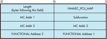
9.7.7 IO$M_UPDATE_MAP Functional Modifier to IO$_SETMODE
Using Token Ring only, the IO$M_UPDATE_MAP qualifier,
when used with IO$_SETMODE, manipulates the adapter's functional
address mapping table. Figure 9-15 shows the format of the P2 buffer for this operation.
This QIO requires PHY_IO privilege.
Figure 9-15 Format of IO$M_UPDATE_MAP Setmode P2 Buffer
The subfunction is one of the following:
NMA$C_MAP_CHANGE —
This function adds or changes a mapping in the functional address
table. If the specified multicast entry does not exist, an entry is
created with the specified functional address mask. If the specified
multicast entry does exist, the corresponding functional address mask
is changed to the specified mask. All users who currently have the
multicast enabled when the functional mask is changed will automatically
update the functional address table as part of this operation.
Possible errors returned include the following:
SS$_DEVICEFULL —
This error indicates that there is insufficient space in the mapping
table to complete the request. The multicast to functional address
mapping table has 200 entries.
NMA$C_MAP_DELETE —
This function deletes the specified MC address in the table. For this
function, the functional address mask is not required to pass the
P2 buffer. If the functional address mask is passed, its contents
are ignored.
Possible errors returned include
the following:
SS$_BADPARAM —
This error indicates that the specified multicast address cannot be
found in the table.
The following example maps multicast address AB-01-01-01-02-03
to the functional address 03-00-00-01-00-00 for device ICA0:.
9.7.8 IO$M_ROUTE Functional Modifier to IO$_SETMODE
For Token Ring only, the IO$M_ROUTE qualifier,
when used with IO$_SETMODE, manipulates the source routing cache table.
This command is successful only when source routing is enabled. Source
routing is enabled with the set mac qualified set mode QIO. Figure 9-16 shows the
format of the P2 buffer. This QIO requires the PHY_IO privilege.
Figure 9-16 Format of the IO$M_ROUTE P2 Buffer
The subfunction is one of the following:
NMA$C_SR_ADD —
This function adds or changes a source routing cache entry. It enters
the LAN address into the table with the enclosed routing information.
The routing information string format is documented in “Token Ring Frames ” . If RI_size
is passed as 0, the entry is created (or modified) to be in the EXPLORING
state (this is useful for users who are doing their own source routing).
If the RC 'Lth' field is 0, the LAN address is entered in
the table as being in the local state.
Possible
errors returned include:
SS$_INSFMEM — The
source routing cache is full.
SS$_BADPARAM —
An invalid RI string was passed or invalid sizes were passed.
SS$_IVMODE — Source
routing is not enabled.
NMA$C_SR_DELETE —
This function deletes a source routing cache entry. The RI_size and
the routing information string are not required for this QIO. If one
or both of the fields are passed for this operation, they are ignored.
The result of this command is to put the entry into the deleted state.
When the entry goes into the deleted state, it is deleted within 10
minutes.
Possible errors returned include
the following:
SS$_BADPARAM —
The requested entry could not be found.
9.7.9 Sense Mode and Sense Characteristics
The sense mode function returns the port attributes in
the specified buffer. These attributes include the device characteristics
described in “LAN Device Information” and, with the exceptions noted below, the attributes listed in Table 9-33.
The following combinations of function code and
modifier are provided:
IO$_SENSEMODE!IO$M_CTRL—Read
characteristics
IO$_SENSECHAR!IO$M_CTRL—Read
characteristics
IO$_SENSEMODE!IO$M_SENSE_MAC—Medium
specific characteristics
IO$_SENSEMODE!IO$M_SHOW_MAP—Returns
current functional address to multicast address mapping (Token Ring
only)
IO$_SENSEMODE!IO$M_SHOW_ROUTE—Returns
current source routing cache table (Token Ring only)
These functions take the following device- or
function-dependent arguments:
P1—The address
of a two-longword buffer where the device characteristics are stored.
(Figure 9-17 shows the format
for, and “LAN Device Information” describes the contents of, the P1 buffer.) The P1 argument is optional.
P2—The address
of a quadword descriptor where the attributes buffer is stored. The
first longword of the descriptor is the buffer length; the second
longword is the address of the buffer. The P2 argument is optional.
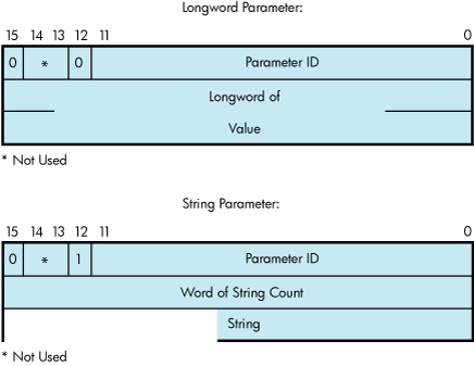
The P2 buffer is not read by the LAN driver. The
driver stores the port's attributes in the buffer, which contains
multiple entries. The format of each entry depends on whether a longword
or a counted string is returned, as shown in Figure 9-18. Each parameter ID contains a string indicator
bit (bit 12) that describes whether the data item is a string or a
longword.
Except for the following differences, P2 returns
the same attributes as those listed in Table 9-31:
All parameters that are
valid for the enabled packet format are returned (see Table 9-32).
The sense-mode P2 buffer
does not return the modifier word for the NMA$C_PCLI_PHA, NMA$C_PCLI_MCA,
and NMA$C_PCLI_DES parameter IDs.
The NMA$C_PCLI_DES parameter
is only returned on Ethernet ports whose access mode is set to “shared
with destination.”
In addition to the parameter
IDs listed in Table 9-31, the sense-mode P2 buffer contains the following parameter IDs:[2]
Parameter ID
Meaning
NMA$C_PCLI_FCA
List of the currently
enabled functional addresses (Token Ring only). Each 32-bit entry
corresponds respectively with the items returned under NMA$C_PCLI_MCA.
NMA$C_PCLI_HWA
Hardware address. Describes the value for the hardware
address. The hardware address is the default physical address when
no physical address has been specified and there are no active users
on the controller. NMA$C_PCLI_HWA is returned in the same format as
NMA$C_PCLI_PHA.
NMA$C_PCLI_MBS
Maximum packet length. NMA$C_PCLI_MBS
is a longword, read-only parameter. The value returned reflects the
largest data packet that the application can receive for its packet
format and type of LAN, measured in bytes. The values for Ethernet,
FDDI, and Token Ring are:
Packet Format
Ethernet
FDDI
Token Ring
Ethernet
format without padding
1500
4470
4418
Ethernet
format with padding
1498
4468
4416
802
format with 1-byte CTL field
1497
4475
4423
802E format
1492
4470
4418
The values for
LAN emulation over ATM are:
Packet Format
ATM ELAN size:
1516
4544
9234
Ethernet format
without padding
1500
4528
9218
Ethernet format with
padding
1498
4526
9216
802 format with 1-byte
CTL field
1497
4525
9215
802E format
1492
4520
9210
Figure 9-17 Sense Mode P1 Characteristics Buffer
It is suggested that a size of 250 bytes be used
for the P2 buffer. This allows space for additional parameters that
may be returned in future releases of OpenVMS.
All attributes that fit into the buffer specified
by P2 are returned; however, if all the attributes cannot be stored
in the buffer, the I/O status block returns the status SS$_BUFFEROVF.
The second word of the I/O status block contains the number
of bytes used in the P2 buffer (see “I/O Status Block”).
Figure 9-18 Sense Mode Attribute Buffer
9.7.10 IO$M_SENSE_MAC Functional Modifier to IO$_SENSEMODE
The IO$M_SENSE_MAC qualifier, when used with IO$_SENSEMODE,
returns the parameters specified in “IO$M_SET_MAC Functional Modifier to IO$M_SETMODE”. In addition to the set mac parameters, Table 9-39 shows the
returns of the following parameters:
Table 9-39 Parameters of IO$M_SENSE_MAC
Parameter ID
Meaning
NMA$C_PCLI_T_NEG
The negotiated value
of the token rotation timer (ANSI MAC parameter T_neg) (FDDI only).
NMA$C_PCLI_DAT
The duplicate address
test flag (FDDI only). If set, this indicates that there is another
station on the ring with the same hardware LAN address.
NMA$C_PCLI_UNA
Upstream neighbor's
address (FDDI and Token Ring). This is a string parameter specifying
the 6-byte LAN address of the upstream neighbor. Not all devices may
support this feature.
NMA$C_PCLI_OLD_UNA
The old (previous) upstream
neighbor address (FDDI only). Neighbor addresses change as nodes insert
and deinsert into the ring.
NMA$C_PCLI_UN_DAT
The upstream neighbor's
duplicate address test flag (FDDI only).
NMA$C_PCLI_DNA
The downstream neighbor's
LAN address (FDDI only).
NMA$C_PCLI_OLD_DNA
The old (previous) downstream
neighbor's LAN address (FDDI only).
NMA$C_PCLI_RPS
The current ring purger
state (FDDI only). This longword parameter is one of the following
values:
0 — Off
1 — Candidate
2 — Non-purger
3 — Purger
NMA$C_PCLI_RER
The latest ring error
reason (FDDI only). This longword parameter is one of the following
values:
0 — No Error
5 — Ring Init initiated
6 — Ring Init received
7 — Ring beaconing initiated
8 — Duplicate address detected
9 — Duplicate token detected
10 — Ring purger error
11 — FCI strip error
12 — Ring op oscillation
14 — PC trace initiated
15 — PC trace received
NMA$C_PCLI_NBR_PHY
Neighbor's PHY type
(FDDI only). This longword parameter is one of the following values:
0 — A
1 — B
2 — S
3 — M
4 — Unknown
NMA$C_PCLI_RJR
Ring reject reason (FDDI
only). This longword parameter is one of the following values:
0 — None
1 — Local LCT
2 — Remote LCT
3 — LCT both sides
4 — LEM reject
5 — Topology error
6 — Noise reject
7 — Remote reject
8 — Trace in progress
9 — Trace received-disabled
10 — Standby
11 — LCT protocol error
NMA$C_PCLI_LEE
Link error estimate (FDDI
only). The longword value is a negative exponent of 10 representing
the Link error rate. For example, the value of X represents the error
rate of 10^X.
NMA$C_PCLI_RNG_NUM
The longword value contains the
ring number that the controller is running on (Token Ring only). It
is only valid for a controller that is started, and also only valid
for rings that have a ring parameter server that is configured for
providing this information.
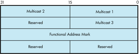
9.7.11 IO$M_SHOW_MAP Functional Modifier to IO$_SENSEMODE
For Token Ring only, the IO$M_SHOW_MAP qualifier,
when used with IO$_SENSEMODE, returns the current setting of the mapping
table. The P2 buffer is filled with the current multicast to functional
address mapping information. The entries are 16 bytes long and are
in the format shown in Figure 9-19. This QIO requires PHY_IO privilege.
Figure 9-19 Format of IO$M_SHOW_MAP P2 Buffer
The multicast address and functional address mask
are returned in canonical format (that is, not bit-reversed). The
following errors may occur:
SS$_BUFFEROVF —
The passed buffer is not large enough to hold all the data required
for the operation.
SS$_BADPARAM —
Not able to get read access to buffer or zero length buffer passed.
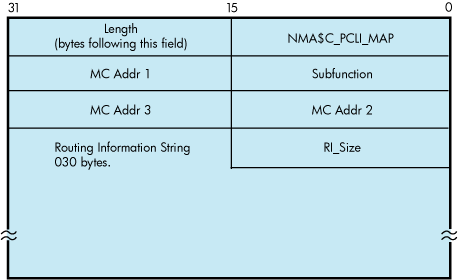
9.7.12 IO$M_SHOW_ROUTE Functional Modifier to IO$_SENSEMODE
For Token Ring only, the IO$M_SHOW_ROUTE qualifier,
when used with IO$_SENSEMODE, returns the current value of the source
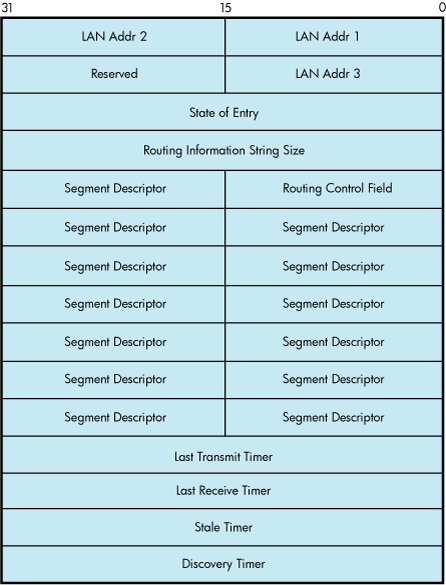
routing cache table. Each entry is 64 bytes long. Figure 9-20 shows
the format of the returned P2 buffer.
Route is known and the
route is stored in the routing information string.
5
EXPLORING
Route to the address is currently being explored.
The LAN address is returned in canonical format
(that is, not bit-reversed). The timers are recorded as seconds before
expiration. The transmit and receive timers are initialized from the
NMA$C_PCLI_A_TIM parameter, the discovery timer is initialized from
the NMA$C_PCLI_ROUTEDIS parameter, and the stale timer is initialized
to 10 minutes (600 seconds). The following errors may occur:
SS$_BUFFEROVF —
The passed buffer is not large enough to hold all the data required
for the operation.
SS$_BADPARAM —
Not able to get read access to buffer or zero length buffer passed.
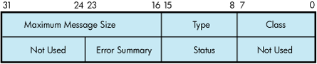
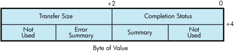
9.7.13 I/O Status Block
The I/O status block
(IOSB) for all LAN driver functions is shown in Figure 9-21. Appendix A lists the completion status returned for these
functions. (The OpenVMS system messages documentation provides explanations
and suggested user actions for these status codes.)
Figure 9-21 IOSB Contents
The first longword of the IOSB returns, in addition
to the completion status, either the size (in bytes) of the data transfer
or the size (in bytes) of the attribute buffer (P2) returned by a
sense mode function. The second longword returns the unit and line
status bits listed in Table 9-26 and the error summary bits listed in Table 9-27.